Mold manufacturing process for reliable plastic parts
What mold manufacturing covers
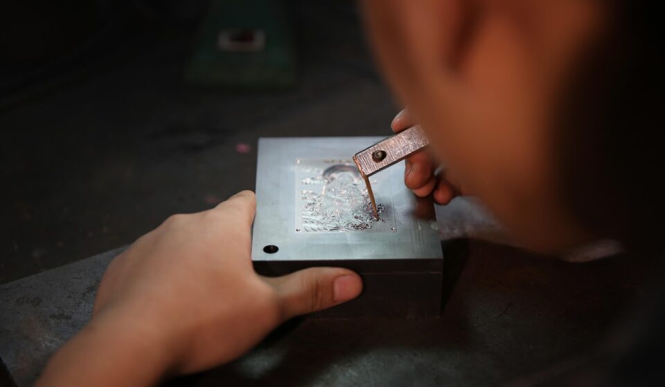
Mold manufacturing is the process of designing, machining, finishing, assembling and validating a tool that repeatedly forms parts from plastic, metal, rubber or composite material. In plastic part production, the mold is more than a block with a cavity. It defines the final geometry, controls material flow, removes heat, releases the part and protects dimensional repeatability over many cycles. Within the wider family of manufacturing processes, mold making is a critical link between product design and mass production because early tooling decisions can be expensive to change later.
This article focuses mainly on molds for plastic injection molding, while noting principles that also apply to compression molding, transfer molding, die casting and related tooling. A reliable mold is usually the result of controlled decisions made before machining begins, not a series of repairs after the first trial.
The mold manufacturing workflow
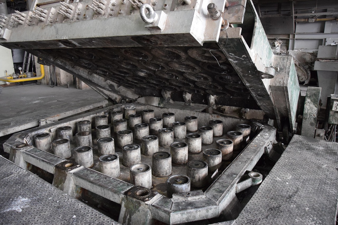
A professional mold manufacturing workflow usually moves from product review to tool design, machining, assembly, trial and production approval. The exact sequence varies by factory and part type, but the risk pattern is consistent: the earlier a problem is found, the cheaper it is to solve.
| Stage | Main decision | Typical output |
|---|---|---|
| Part review | Confirm geometry, material, tolerance, appearance and production volume | Design for manufacturing notes and open issues |
| Mold concept | Select cavity count, parting line, gate location, runner type, ejection and cooling strategy | Tool concept and estimated cost drivers |
| Detailed mold design | Engineer plates, inserts, sliders, lifters, vents, cooling circuits and standard components | 3D tool model and 2D manufacturing drawings |
| Material preparation | Choose tool steel, aluminum, inserts and purchased components | Ordered tool material and component list |
| Machining and EDM | Cut cavities, cores, holes, shutoffs, ribs and precision features | Machined mold plates and inserts |
| Finishing and fitting | Polish, texture, fit moving parts and verify shutoff contact | Assembled trial-ready mold |
| Mold trial | Run sample parts and check process stability | Dimensional report, defect list and correction plan |
| Approval and maintenance | Freeze the process window and define upkeep requirements | Production release and maintenance schedule |
The part review is often the most valuable stage. Wall thickness variation, sharp internal corners, insufficient draft, undercuts, tight cosmetic requirements and unrealistic tolerances can all force more complex tooling. If these issues are identified before the mold concept is locked, engineers can often reduce cost and improve production stability without compromising the part’s function.
Design choices that control mold quality
Part geometry and tolerance planning
A mold can only reproduce what the part design and molding process allow. Draft angles help the part release from the cavity. More uniform wall thickness helps reduce sink, voids and uneven shrinkage. Ribs and bosses must be strong enough for function but designed to avoid heavy local mass. Shutoff surfaces, snap fits and sealing features need close review because small mismatch can create flash, wear or assembly problems.
Tolerance planning is also a mold manufacturing issue, not only a drawing issue. The public record for ISO 20457:2026 describes the standard as covering geometrical and dimensional tolerances and acceptance conditions for plastic molded parts. It applies to non-porous molded parts made from thermoplastics, thermoplastic elastomers and thermosets using processes such as injection molding, injection compression molding, transfer molding, compression molding and rotational molding. In practice, this type of standard helps design and manufacturing teams discuss which tolerances are functionally necessary and which may be too narrow for the selected material, tool and process.
Gating, venting and material flow
Gate position affects how the cavity fills, where weld lines form, how packing pressure reaches thick sections and where visible gate marks remain. A gate that is convenient for machining may not be best for appearance or strength. Runner type also matters. A cold runner can be simpler and lower in initial cost, while a hot runner may reduce material waste and improve automation in higher-volume production. The trade-off is added system cost, maintenance and temperature-control requirements.
Venting deserves the same level of attention. If air and gases cannot escape from the cavity, the process may produce burn marks, short shots, weak weld lines or inconsistent fill. Vent depth, vent location and cleaning access should be considered during mold design rather than added randomly during troubleshooting.
Cooling and dimensional stability
Cooling is one of the main levers for cycle time and dimensional consistency in injection molding. Cooling channels that are too far from hot areas can create temperature imbalance, longer cycle time and warpage. Traditional drilled channels are cost-effective for many molds, but they are limited to straight passages and accessible angles. Complex cores, deep ribs and uneven wall sections may need baffles, bubblers, high-conductivity inserts or more advanced channel layouts.
Published research on metal additive manufacturing for injection mold inserts has reported that conformal cooling channels can improve cooling performance compared with traditional channels in specific test conditions. One study reported up to 62.9% better cooling performance in its evaluated design context. That figure should not be treated as a universal result for every mold, but it explains why conformal cooling is now part of serious tooling discussions for difficult thermal problems.
Conventional machining, EDM and additive tooling
Most production molds still depend on conventional subtractive manufacturing. CNC milling, turning, drilling and grinding create the plates, inserts, cores and major geometry. Electrical discharge machining, commonly called EDM, is used where milling cannot easily reach, such as deep ribs, narrow slots, sharp internal features and hard tool steel details. Wire EDM can produce precise through-features and inserts, while sinker EDM can create cavity details using shaped electrodes.
Additive manufacturing does not replace these methods in most mold shops. Instead, it expands the design options for selected inserts and complex cooling layouts. NIST’s Manufacturing Extension Partnership has described additive manufacturing as useful for making molds, mold inserts and patterns, especially where it can reduce process steps or enable design features that are difficult to machine conventionally. For tooling teams, the practical question is not whether additive manufacturing is modern, but whether it solves a measurable problem in the mold.
When additive tooling makes sense
Additive tooling is most persuasive when a mold has concentrated heat, complex geometry or space constraints that prevent efficient conventional cooling. It may also be useful for prototype inserts, short-run tooling, casting patterns or hybrid tools that combine a machined mold base with printed local inserts. The strongest business case usually comes from measurable cycle-time reduction, improved part stability, reduced scrap or a design that cannot be achieved with drilled channels.
Where conventional tooling remains stronger
Conventional machining remains the logical choice for many simple cavities, flat plates, standard water lines and high-polish surfaces. Additive inserts may require heat treatment, machining, surface finishing and inspection after printing. Powder-bed metal processes can also introduce considerations around porosity, build orientation, support removal and material qualification. For a simple part with no thermal bottleneck, a printed insert may add cost without improving production performance.
Tolerance, validation and acceptance in production
A mold is not finished when the last cavity is polished. It is finished when it can produce acceptable parts within a stable process window. The first mold trial often reveals issues that CAD review could not fully predict, including actual shrinkage, venting behavior, weld-line visibility, ejection marks, flash, sink, warpage and cooling imbalance. See also: cnc and robotics.
| Validation item | What to check | Why it matters |
|---|---|---|
| Dimensional inspection | Critical dimensions, flatness, hole position and assembly fit | Confirms whether the part meets the drawing and functional requirements |
| Visual inspection | Gate vestige, weld lines, flow marks, gloss, texture and scratches | Protects cosmetic and customer-facing requirements |
| Ejection behavior | Sticking, drag marks, deformation and ejector balance | Prevents cycle interruption and part damage |
| Cooling performance | Hot spots, cycle time, water flow and temperature balance | Controls repeatability, warpage and productivity |
| Process window | Fill, pack, hold, cooling and clamping conditions | Shows whether the mold is robust or only works under narrow settings |
| Safety and access | Guarding, handling, lifting points and maintenance access | Reduces risk during operation, mold changes and repair |
Machine safety should not be treated as separate from mold acceptance. OSHA guidance for horizontal injection molding machines describes the process as converting plastic pellets into molten material, injecting the material into a mold and cooling it into the final part. OSHA’s plastics industry materials also emphasize guarding, training and safety practices for workers who operate or work around injection molding equipment. Tooling teams should therefore consider safe lifting, secure clamping, clear access to water and electrical connections, and maintenance-friendly layouts during mold design.
Cost, lead time and risk drivers
Mold cost is shaped by far more than part size. Key drivers include cavity count, tool material, expected production volume, surface finish, tolerance level, parting-line complexity, number of sliders or lifters, hot-runner requirements, texture, polishing, cooling complexity and inspection needs. A single-cavity prototype mold and a hardened multi-cavity production mold may look similar to a non-specialist, but they are different engineering projects.
Lead time is affected by the same factors. Tool steel procurement, electrode manufacture, heat treatment, polishing, texturing, mold trials and correction loops all add time. Late design changes are especially costly after machining has started. Moving a gate, changing wall thickness, adding an undercut or tightening a tolerance can require insert replacement or major rework.
The lowest initial tool quote is not always the lowest manufacturing cost. A mold that needs frequent repair, runs a slow cycle, produces excess scrap or cannot hold dimensions will cost more during production. A better purchasing question is whether the proposed mold concept matches the part’s material, tolerance, annual volume, cosmetic requirements and maintenance expectations.
Practical checklist before cutting steel
Before mold manufacturing moves into machining, the engineering team should be able to answer a practical set of questions. If the answers are unclear, the mold may still be buildable, but the risk of rework increases.
- Have the functional dimensions been separated from non-critical dimensions?
- Has the material grade been confirmed, including shrinkage behavior and processing temperature range?
- Are wall thickness, ribs, bosses and corners suitable for molding?
- Is there enough draft for reliable ejection without damaging texture or polished surfaces?
- Has the parting line been reviewed for appearance, flash risk and assembly impact?
- Are gate locations acceptable for strength, appearance and post-processing?
- Can vents be placed and cleaned without weakening critical shutoffs?
- Does the cooling design address thick sections and likely hot spots?
- Are sliders, lifters and inserts designed for wear, access and maintenance?
- Has the inspection plan been agreed before the first trial parts are produced?
This checklist does not replace engineering review, simulation or supplier experience. It does, however, help align product designers, tooling engineers, molders and quality teams around the same definition of success.
Frequently asked questions
What is the difference between mold manufacturing and injection molding?
Mold manufacturing is the creation of the tool. Injection molding is the production process that uses that tool to form parts. A mold maker designs and builds the cavity, core, cooling, ejection and mechanical features. A molder installs the tool in a machine, processes the material and produces parts under controlled conditions.
Which materials are commonly used for molds?
Production molds are commonly made from tool steels selected for strength, wear resistance, polishability and heat-treatment response. Aluminum may be used for prototypes, bridge tooling or lower-volume programs where fast machining and thermal conductivity are valuable. Inserts may use different materials from the main mold base when local wear, cooling or repairability requires it.
Are 3D-printed molds replacing machined molds?
No. Additive manufacturing is better understood as a complementary tooling method. It can be valuable for inserts, prototype tools, patterns and conformal cooling features, but machined steel molds remain the standard choice for many high-volume, high-polish and tight-tolerance production applications.
Why do mold trials find problems even after careful design?
Real molding combines material behavior, machine settings, tool temperature, pressure, part geometry and cooling conditions. Simulation and design review reduce risk, but they do not eliminate all uncertainty. Trials provide physical evidence, including actual shrinkage, surface behavior, ejection balance and process stability.
How can buyers reduce mold manufacturing risk?
Buyers can reduce risk by freezing the part design before machining, sharing clear functional requirements, approving a realistic tolerance plan, reviewing the mold concept early and defining inspection criteria before the first sample run. Clear communication before steel is cut is usually cheaper than correction after the first trial.