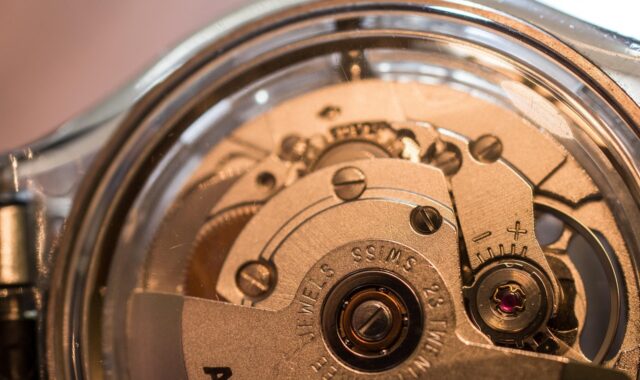
What perfect precision engineering means in modern manufacturing

Precision is a system, not a slogan
In manufacturing, perfect precision engineering is best understood as a disciplined pursuit of fit-for-function accuracy. It is not a claim that every part can be produced with zero deviation. Real parts vary because machine tools, materials, cutting tools, temperature, fixtures, operators, and measurement systems all introduce change. The task is to define which features require control, set tolerances that support product function, build processes that can hold those tolerances repeatedly, and verify results through reliable metrology.
This approach is more useful than simply making every dimension tighter. It connects engineering intent, machining strategy, inspection planning, and quality feedback into one controlled system. For related manufacturing topics, see our precision engineering section.
Why perfect precision starts by defining allowable variation
Precision engineering starts with a practical truth: no production process makes identical parts. Even high-end CNC machining, grinding, EDM, lapping, additive finishing, and optical metrology operate within variation. A tolerance is the agreed boundary between acceptable and unacceptable variation. If the tolerance is too loose, the part may not assemble, seal, rotate, locate, or perform safely. If it is tighter than necessary, cost rises through slower machining, more scrap, longer inspection time, special tooling, and greater supplier risk.
A strong precision strategy therefore starts with function. Engineers should identify which features drive performance and which features only need ordinary manufacturing control. Typical critical areas include bearing seats, sealing surfaces, datum interfaces, gear centers, optical mounts, sliding fits, thin-wall alignment features, and holes that control assembly stack-up. Noncritical surfaces may still require good workmanship, but they do not always need micrometer-level control.
This distinction is central to perfect precision engineering. Perfection is not the removal of all variation. It is the alignment of variation with product risk. A well-designed part tells the manufacturer where precision matters, where standard process capability is enough, and where inspection evidence is required.
The specification layer turns function into measurable requirements
Functional requirements come before tighter numbers
A drawing or model should translate product function into measurable requirements. The datum structure, tolerance values, surface finish, material condition, and inspection method need to work together. A flatness tolerance on a sealing face, for example, communicates a different manufacturing challenge from a simple plus-minus thickness tolerance. When part orientation and datums matter, a positional tolerance on a hole pattern usually communicates assembly intent more clearly than several independent coordinate dimensions.
A common mistake is tightening dimensions because a part is important, without asking which geometric error would actually cause failure. That can create expensive specifications that are difficult to inspect and still fail to control the real functional risk. Better specifications place tight control on the features that influence load paths, motion, sealing, heat transfer, optics, or assembly alignment.
GD&T provides a shared manufacturing language
Geometric dimensioning and tolerancing gives designers, machinists, and inspectors a common language for shape, orientation, location, run-out, and profile control. ASME lists Y14.5-2018 as the replacement for ASME Y14.5-2009 for dimensioning and tolerancing. ISO describes ISO 1101:2017 as defining the symbol language for geometrical specification of workpieces and the rules for interpreting those specifications.
Those standards do not automatically make a process precise. Their value is that they reduce ambiguity. A supplier can plan machining datums, inspection setups, CMM routines, and fixture concepts around the same geometric meaning intended by the design team. For high-precision parts, this shared interpretation often prevents more quality problems than adding another decimal place to a linear dimension.
The process layer controls variation before inspection
Inspection can identify a bad part, but it cannot make a process stable by itself. In high-value precision manufacturing, process control has to happen before the part reaches final measurement. That includes machine qualification, fixture design, tool selection, thermal planning, cutting strategy, operator training, and feedback from in-process checks.
- Machine condition: Backlash, spindle runout, axis squareness, guideway wear, servo behavior, and vibration all influence finished geometry.
- Thermal behavior: Heat from spindles, coolant, cutting, ambient temperature, and operator handling can change dimensions enough to matter in close-tolerance work.
- Fixturing and datums: A precise tool path cannot compensate for a part that is clamped inconsistently or referenced from the wrong surface.
- Tool wear: Cutting edges change during production, affecting size, finish, burr formation, and force-related deflection.
- Material behavior: Residual stress, hardness variation, anisotropy, and heat treatment distortion can shift dimensions after machining.
- Programming strategy: Tool engagement, climb versus conventional cutting, finishing allowance, interpolation, and compensation values all affect repeatability.
For machine tools, ISO 230-1:2012 specifies methods for testing geometric accuracy under no-load or quasi-static conditions. That type of machine assessment is not the same as proving every production part is good, but it supports the foundation of a capable process. A machine that cannot hold stable geometry will force inspection teams to catch problems that should have been prevented earlier.
The measurement layer proves conformance with uncertainty
Traceability belongs to the measurement result
Metrology is where precision claims become evidence. Calipers, micrometers, height gauges, surface plates, optical comparators, laser trackers, CMMs, and vision systems all have limits. A measurement result is useful only when the method, equipment, environment, operator technique, calibration status, and uncertainty are appropriate for the tolerance being checked.
NIST policy explains metrological traceability as a property of a measurement result, not merely a label on an instrument. In practical terms, the result should connect to a recognized reference through a documented calibration chain, with each step contributing uncertainty. This matters because a certificate alone does not prove that a specific inspection result is fit for a tight tolerance. The measuring setup must be suitable for the feature, the tolerance zone, the surface condition, and the required confidence.
Decision rules make pass and fail judgments less ambiguous
When tolerance limits are close to measurement uncertainty, pass and fail decisions become more complex. ISO 14253-1:2017 addresses decision rules for verifying conformity or nonconformity by measurement. This is important in precision engineering because two organizations can measure the same part and reach different conclusions if they do not agree on uncertainty, guard bands, sampling, and acceptance rules.
A notable measurement-management update is ISO 10012:2026, which ISO identifies as replacing ISO 10012:2003. The newer edition focuses on requirements for a measurement management system that gives confidence in the validity and reliability of measurement results. For manufacturers, the practical message is clear: measurement is not just equipment ownership. It is a managed process covering people, procedures, calibration, environment, records, and continual improvement. See also: cnc and robotics.
A practical framework for precision engineering decisions
The most useful precision programs connect design, production, and inspection through a visible decision chain. The following framework can help teams avoid treating precision as a late-stage quality problem.
| Decision point | Question to answer | Practical output |
|---|---|---|
| Function | Which features affect fit, motion, sealing, load, optics, or safety? | Critical-to-function feature list |
| Specification | Which tolerance type communicates the real functional limit? | Clear size, form, orientation, location, or profile requirement |
| Process | Can the chosen machine, tool, fixture, and sequence repeatedly hold the requirement? | Manufacturing plan with known control points |
| Measurement | Can the inspection method resolve the tolerance with acceptable uncertainty? | Inspection plan, calibrated equipment, and decision rule |
| Feedback | What data shows drift before parts become nonconforming? | Control charts, tool offsets, maintenance actions, or design review |
This framework also helps manage cost. A tolerance should not be approved in isolation. It should be reviewed together with process capability, measurement capability, production volume, material stability, and supplier experience. If any link is weak, the right response may be a design change, a different datum scheme, a revised inspection plan, a process trial, or a more realistic tolerance.
Where precision investment usually creates the most value
Precision investment is most valuable when small geometric errors create large functional consequences. Examples include rotating assemblies, medical and laboratory devices, aerospace mechanisms, semiconductor and optics equipment, robotics joints, fluid-control components, and high-speed automation. In these applications, the cost of poor alignment, leakage, vibration, friction, or assembly rework can exceed the cost of better engineering control.
More precision, however, is not always better. If a tolerance is tighter than the product needs, tighter than the process can repeat, or tighter than the inspection method can confidently verify, it may increase risk rather than reduce it. The better question is not how tight the part can be made. The better question is what level of control protects product function while still allowing a reasonable manufacturing and inspection path.
That is why successful precision programs often invest first in design clarity, datum discipline, thermal stability, fixturing, tool-life control, and measurement planning. Expensive equipment can help, but it cannot compensate for unclear specifications or unstable processes.
Common failure modes in precision programs
Many precision problems are not caused by a lack of advanced machinery. They are caused by gaps between design intent, manufacturing reality, and inspection practice. Common failure modes include:
- Applying tight plus-minus tolerances where geometric tolerances would better describe function.
- Choosing datums that are convenient on the drawing but difficult to repeat in fixtures or inspection setups.
- Ignoring thermal expansion when measuring close-tolerance parts in uncontrolled environments.
- Using calibrated equipment without confirming that the method is suitable for the tolerance.
- Inspecting final parts only, instead of monitoring process drift during production.
- Failing to communicate acceptance rules between customer, supplier, and inspection teams.
Solving these issues usually requires cross-functional review rather than a single technical fix. Design, manufacturing engineering, quality, purchasing, and suppliers need the same understanding of what precision means for the part in question.
Frequently asked questions
Is perfect precision engineering the same as zero tolerance?
No. Zero tolerance is not a practical manufacturing condition. Perfect precision engineering means defining the right tolerance for the function, controlling the process to meet it repeatedly, and verifying conformance with an appropriate measurement system.
What is the difference between precision and accuracy?
Precision describes repeatability or consistency. Accuracy describes closeness to the intended value. A process can be precise but inaccurate if it repeats the same offset, and it can be accurate on average but not precise if results scatter widely.
Why is GD&T important in precision manufacturing?
GD&T helps communicate the geometry that actually affects function, such as position, flatness, perpendicularity, profile, and run-out. It also connects specifications to datums, which makes machining and inspection interpretation more consistent.
How often should measuring equipment be calibrated?
Calibration frequency depends on equipment type, usage, environment, historical stability, risk, and customer or regulatory requirements. A fixed calendar interval is common, but high-risk measurements may require additional checks, interim verification, or tighter control of measurement conditions.
Should every precision part be inspected on a CMM?
Not always. A CMM is powerful, but it is not the right answer for every feature. Some characteristics are better checked with functional gauges, surface measurement tools, optical systems, in-process probing, or dedicated fixtures. The inspection method should match the tolerance, geometry, surface, production volume, and required uncertainty.