Gear manufacturing guide for process selection and quality control
What gear manufacturing must achieve
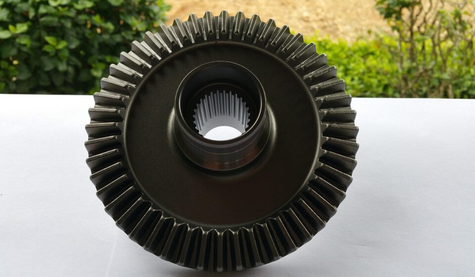
Gear manufacturing is more than cutting teeth into a round blank. It is a controlled sequence of design review, material selection, blank preparation, tooth generation, edge treatment, heat treatment, finishing and inspection. The goal is to produce gears that transmit torque smoothly, meet the specified tooth geometry, withstand contact and bending loads, and run within acceptable noise and vibration limits. For engineers comparing manufacturing processes, the key question is not simply which cutting method is fastest. It is which process route can meet the required accuracy, material condition, production volume and cost without introducing avoidable distortion, burrs, inspection gaps or finishing problems.
A sound gear route is defined before the first chip is cut. Gear type, module or diametral pitch, pressure angle, helix angle, face width, bore datum, material, hardness target and accuracy class all influence process selection. Spur and helical gears, internal ring gears, bevel gears and worm gears may require different machines, cutters and inspection methods. Even within one gear family, a prototype, a replacement gear and a high-volume transmission gear can justify very different manufacturing choices.
The typical gear manufacturing route
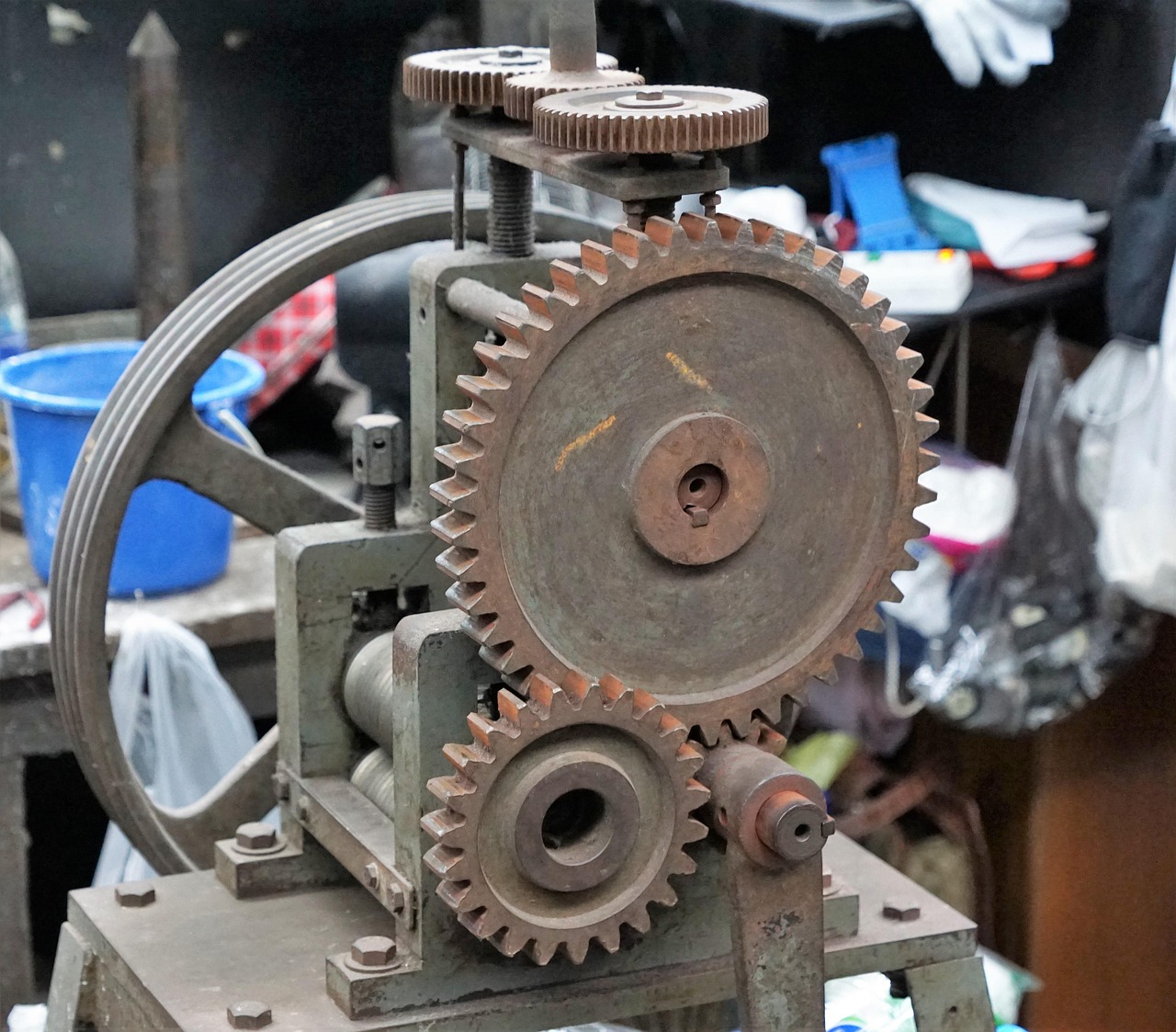
Most machined metal gears follow a route that can be simplified into six stages: define the gear geometry, prepare the blank, generate or form the teeth, remove burrs and condition edges, apply heat treatment if required, and finish or inspect the gear to specification. The exact order depends on material, hardness and quality target. Some gears are used after soft cutting and deburring. Others are cut oversize, hardened and then ground, honed or lapped to restore accuracy after heat-treatment movement.
Design inputs before process planning
The process plan starts with the drawing. A gear drawing should define more than outside diameter and tooth count. It should identify the datum structure, bore and face tolerances, tooth thickness or backlash requirement, flank accuracy standard, surface finish requirements, heat-treatment specification, hardness range and any tooth modifications such as crowning, tip relief or lead correction. If these details are vague, the manufacturer may be able to make a gear-shaped part, but the part may not perform correctly in a loaded gearbox.
Manufacturability also has to be reviewed early. A shoulder too close to the tooth area may block a hob. An internal spline may be better suited to shaping, broaching or skiving than external hobbing. A grinding wheel may need relief space to avoid creating a notch in the root area. These details matter because late changes to shaft layout, gear width or datum strategy can cost more than the cutting operation itself.
Blank preparation and datum control
The gear blank establishes the physical foundation for the tooth geometry. Turning, boring, facing and, in some cases, milling create the surfaces used for workholding and inspection. Concentricity between the bore, faces and outside diameter matters because tooth accuracy is measured relative to the gear axis. If the blank is unstable or poorly referenced, a precise cutting machine cannot fully correct the error. For high-performance gears, blank quality, material cleanliness, forging or bar-stock condition, and stress relief can also influence heat-treatment behavior and final accuracy.
Main tooth-forming methods and where they fit
Gear teeth can be produced by generating, forming or finishing methods. Generating processes create the involute form through coordinated motion between the tool and workpiece. Forming methods use a tool shaped closer to the tooth space. Finishing methods remove smaller amounts of material to improve accuracy, surface finish or contact behavior.
| Process | Common use | Strengths | Limitations |
|---|---|---|---|
| Hobbing | External spur and helical gears | Productive, versatile and widely used for cylindrical gears | Needs tool clearance and may be limited near shoulders or interfering features |
| Shaping | Internal gears, external gears near shoulders, splines | Useful where hobs cannot pass through or overrun | Generally slower than hobbing for many external gear jobs |
| Broaching | High-volume internal gears and splines | Fast cycle time once tooling is justified | Dedicated broaches are expensive and less flexible for design changes |
| Power skiving | Internal and external gears, especially when integration with turning or milling is valuable | Can be productive and can work close to shoulders with the right machine | Requires rigid machines, accurate synchronization and well-developed parameters |
| Form milling | Low-volume, repair, large or special gears | Flexible and practical when dedicated gear machines are not justified | Often slower and may require more inspection and finishing |
| Grinding | Hardened precision gears | Improves accuracy and surface finish after hardening | Higher cost and risk of thermal damage if poorly controlled |
Hobbing remains a core method in gear manufacturing because it can generate many external spur and helical gears efficiently. The hob and workpiece rotate in a fixed relationship while the tool feeds across the face width. The process is especially attractive for repeat production where setup, cutter selection and feed strategy are stable. Shaping uses a reciprocating cutter that meshes with the workpiece. It is often selected for internal gears or for external gears where a shoulder prevents normal hob overrun.
Broaching can be highly efficient for high-volume internal forms, but it commits the producer to dedicated tooling. Power skiving has gained attention because it combines aspects of hobbing and shaping while supporting both internal and external teeth. Its advantage is strongest when the machine, tool and control system can maintain accurate synchronization between cutter and workpiece. For one-off or very large gears, form milling and profile milling may still be practical, especially when the cost of dedicated gear tooling is not justified.
Heat treatment, edge control and finishing
Many gears require surface hardening to carry higher loads and resist wear. Carburizing, induction hardening, nitriding and through hardening are common choices, depending on the steel, tooth size, duty cycle and case-depth requirement. Carburized gears are often quenched and tempered, producing a hard case over a tougher core. The benefit is higher load-carrying capacity; the risk is distortion. Bore size, lead, involute profile, pitch and runout can all shift during heat treatment.
Why chamfering and deburring matter
Burrs are not cosmetic defects in precision gearing. A sharp edge can chip after hardening, damage mating teeth, contaminate lubricant or shorten the life of a finishing tool. Chamfering and deburring are therefore important steps between tooth cutting and hard finishing. In e-drive and other low-noise applications, edge condition receives closer attention because small tooth defects can contribute to transmission error, noise or premature surface distress.
Hard finishing after heat treatment
Finishing after hardening is used when soft cutting alone cannot hold the required geometry. Gear grinding is one of the most common hard-finishing routes for precision gears. It can correct heat-treatment distortion and improve flank finish, but it requires careful control of stock allowance, wheel condition, coolant and grinding burn inspection. Honing is often used to improve surface texture and noise behavior. Lapping is common for some bevel gear sets where the mating pair is finished together to refine the contact pattern.
The finishing allowance must be built into the earlier process. Too little stock may leave heat-treatment distortion uncorrected. Too much stock increases cycle time and can remove beneficial case depth or create a root condition that weakens the tooth. A strong process plan treats soft cutting, heat treatment and finishing as one connected route rather than separate purchasing steps.
Accuracy standards and inspection points
Gear quality grades are useful, but they are often misunderstood. A quality or accuracy class does not automatically describe every feature of a gear. It normally focuses on defined geometric deviations such as pitch, profile, helix or composite variation. Material cleanliness, hardness pattern, surface integrity, nicks, burrs, gearbox alignment and lubrication are separate issues that can still determine whether the gear performs well. See also: cnc and robotics.
AGMA and ISO standards provide common language for gear accuracy and inspection. ISO 1328 is widely referenced for cylindrical gear flank tolerance classification, while AGMA publications provide related standards and information sheets for cylindrical, bevel, worm and inspection topics. These standards help buyers and manufacturers communicate tolerance classes, measurement methods and acceptance criteria. They should be specified carefully, because older AGMA quality-number systems and ISO grade systems do not always map directly to each other.
Inspection usually combines general dimensional checks with gear-specific measurement. Common checks include bore size, face runout, outside diameter, tooth thickness, span or over-pin measurement, pitch deviation, total cumulative pitch deviation, profile deviation, helix deviation and radial composite variation. Coordinate measuring machines and gear measuring centers are often used for higher accuracy work. In September 2022, NIST reported that it had resumed ultra-accurate gear-related measurement services for customers after a long interruption, highlighting how important traceable metrology remains for precision gear manufacturing.
How to choose a gear manufacturing route
No single route fits every gear. Selection should balance geometry, quantity, accuracy, material, hardness, equipment access and inspection cost. The table below summarizes typical decisions, but each application should still be confirmed against the drawing and service conditions.
| Application situation | Likely route | Reason |
|---|---|---|
| Medium-volume external spur or helical gear, moderate accuracy | Turn blank, hob teeth, chamfer, deburr and inspect | Hobbing is productive and may meet final accuracy without hard finishing |
| High-load carburized transmission gear | Blank machining, pre-cut teeth, chamfer, carburize, quench, grind or hone, inspect | Hard finishing corrects distortion and improves flank quality |
| Internal ring gear in production volume | Shape, broach or skive depending on volume and flexibility needs | Internal geometry limits conventional hobbing and may justify specialized tooling |
| Prototype or replacement gear | CNC milling, shaping or hobbing with flexible inspection | Tooling cost and lead time may matter more than the fastest cycle time |
| Low-noise electric drive gear | Controlled hobbing or skiving, precise chamfering, heat treatment, grinding or honing, detailed flank inspection | Noise behavior depends on small geometry and surface deviations |
Production volume often drives the economic decision. A broach, special hob or dedicated fixture can be justified when the same gear will be made many times. For short runs, flexible tooling and longer cycle times may be more economical. Accuracy changes the calculation as well. A process that looks inexpensive at the tooth-cutting stage may become costly if it creates distortion, burrs or stock variation that later require heavy correction.
Common risks that increase cost or scrap
- Unclear accuracy specification: A drawing that states only “AGMA quality” or “high precision” leaves room for disagreement. Specify the standard, grade and measured elements.
- Poor datum planning: If the inspection datum differs from the manufacturing datum, measured runout and tooth alignment may suffer.
- Insufficient tool clearance: Shoulders, flanges and nearby gear features can block hobbing or finishing tools.
- Uncontrolled heat-treatment distortion: Hardening can move tooth geometry, bore shape and faces. Stock allowance and fixture strategy should reflect this risk.
- Weak burr control: Burrs left before hardening can become hardened defects that are harder to remove later.
- Overreliance on one quality number: Gear performance also depends on material, heat treatment, surface integrity, assembly alignment and lubrication.
Gear manufacturing should be managed as a chain of dependent operations. Cutting accuracy matters, but so do blank stability, edge preparation, thermal processing and measurement capability. A robust route prevents errors from being passed downstream, where they are usually more expensive to fix.
Frequently asked questions
What is the most common gear manufacturing process?
For external spur and helical gears, hobbing is one of the most common and productive methods. It is not the best answer for every gear. Internal gears, gears close to shoulders, very large gears or hardened precision gears may require shaping, broaching, skiving, milling, grinding, honing or lapping.
Why are gears often ground after heat treatment?
Heat treatment can improve hardness and load capacity, but it can also distort the gear. Grinding after hardening removes controlled stock from the flanks to restore profile, lead and pitch accuracy. It can also improve surface finish, although it adds cost and must be controlled to avoid thermal damage.
Is a higher gear accuracy grade always better?
Higher accuracy can reduce transmission error, noise and dynamic loading, but it is not always economically necessary. The right grade depends on speed, load, noise target, gearbox design and inspection budget. Over-specifying accuracy can add cost without improving the actual application.
What should be included on a gear drawing for manufacturing?
A useful drawing should include gear geometry, material, heat treatment, hardness range, datum scheme, tooth thickness or backlash requirement, accuracy standard and grade, surface finish, inspection requirements and any flank modifications. Missing details often lead to rework or disputes.
How does power skiving differ from hobbing?
Hobbing typically uses a hob to generate external cylindrical gears with continuous rotation and axial feed. Power skiving uses a pinion-like cutter at a crossed-axis angle with synchronized tool and workpiece rotation. It can be useful for internal gears and features near shoulders, but it requires suitable machine rigidity, synchronization and process development.