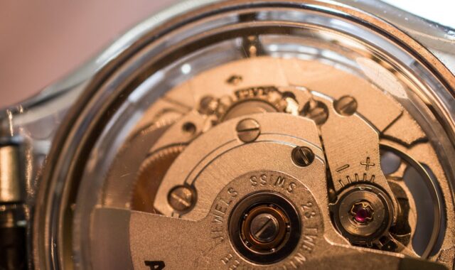
Ultra precision engineering in modern manufacturing from machining to metrology

What ultra precision engineering means in practice
Ultra precision engineering refers to the design and manufacture of parts where very small geometry, surface or position errors can affect product performance. In practice, it is less about quoting one impressive tolerance number and more about managing a controlled chain: stable machines, suitable materials, deterministic processes, clear tolerancing and measurement systems that can prove the result. A 2026 review in npj Advanced Manufacturing makes this point clearly, noting that ultra-precision capability must be interpreted through precision engineering, traceable metrology, uncertainty budgets and control of error sources across the value chain. (nature.com)
That distinction matters for manufacturers. A machine may offer nanometer-scale feedback resolution, but that does not automatically mean the finished part has nanometer-level accuracy. Servo behavior, thermal drift, tool wear, fixture distortion, material response, vibration and measurement uncertainty can all dominate the final result. For readers following precision engineering, ultra precision is best understood as a system discipline, not a single machining capability.

The market pull is clear. Optical components, semiconductor tooling, advanced sensors, photonic devices, medical microfeatures and aerospace metrology hardware all depend on surfaces or geometries that ordinary precision machining may not control well enough. The challenge is that as a part moves toward micrometer, sub-micrometer or nanometer requirements, more assumptions in conventional manufacturing have to be tested.
The process chain is broader than one machine tool
Ultra precision engineering often includes single-point diamond turning, ultra-precision milling or grinding, polishing, lapping, ion-beam finishing, chemical mechanical polishing and, increasingly, hybrid processes. The right route depends on the material, shape, surface finish, functional requirement and production volume. A mirror-like optical insert, for example, may need a different process chain from a wafer chuck, microfluidic mold, precision bearing component or freeform lens.
Single-point diamond turning is one of the most recognizable processes in this field because it can generate optical-quality surfaces on suitable materials. The same 2026 review traces the roots of ultra-precision manufacturing to optical fabrication and single-point diamond turning in the mid-twentieth century, when air-bearing spindles, hydrostatic slides and diamond-tipped cutting tools helped establish deterministic machining of high-performance surfaces. (nature.com)
Even so, diamond turning is not a universal answer. Ferrous alloys can chemically interact with diamond tools and accelerate wear. Brittle materials may require ductile-regime grinding, controlled polishing or assisted machining. Complex freeform surfaces need careful toolpath strategy and compensation. In many production plans, the value lies not in selecting the most advanced process, but in choosing the most stable sequence of processes.
| Process route | Typical role in ultra precision work | Main limitation to manage |
|---|---|---|
| Single-point diamond turning | Optical surfaces, molds and non-ferrous precision components | Tool wear, material compatibility and thermal stability |
| Ultra-precision grinding | Hard, brittle or ferrous materials where diamond turning is unsuitable | Subsurface damage, wheel conditioning and vibration |
| Polishing and lapping | Surface finish improvement and form correction | Edge control, repeatability and process time |
| Ion-beam or chemical mechanical finishing | Very fine correction for optics, wafers and functional surfaces | Throughput, masking strategy and metrology feedback |
| Hybrid assisted machining | Hard-to-cut materials and difficult surface requirements | Process complexity and qualification effort |
Tolerances must be translated into manufacturable requirements
One recurring problem in ultra precision projects is the gap between a design requirement and a manufacturing requirement. A drawing may call out flatness, profile, roundness or position, but the production team still needs to know which feature matters functionally, how it will be inspected and whether the tolerance stack makes physical sense.
ISO 1101:2017 is one of the key international references for geometrical product specifications. ISO describes it as defining the symbol language for geometrical specification of workpieces and the rules for interpretation, providing a foundation for geometrical specification. (iso.org) In the United States and many global supply chains, ASME Y14.5 is also widely used for geometric dimensioning and tolerancing. ASME describes Y14.5 as a guideline for GD&T symbols, rules, definitions, requirements and recommended practices for engineering drawings, model-based data and related documents. (asme.org)
For ultra precision engineering, these standards are not paperwork exercises. They help separate critical functional surfaces from cosmetic or non-critical features. They also help avoid over-constraining a part. Specifying a very tight tolerance everywhere can raise cost, reduce yield and still fail to protect the most important performance characteristic.
A practical specification should answer four questions before manufacturing starts:
- Which surfaces or features directly affect function, alignment, sealing, optical behavior or motion?
- Which tolerance type best expresses that function, such as profile, flatness, roundness, position or runout?
- What measurement method has enough resolution and uncertainty margin to verify the requirement?
- Which environmental conditions, including temperature and fixturing state, define the acceptance condition?
Machine accuracy needs evidence, not assumptions
Ultra precision engineering depends on machines that move repeatably and predictably, but machine capability should be verified rather than assumed from a brochure. ISO 230-2:2014 addresses methods for testing and evaluating the accuracy and repeatability of positioning of numerically controlled machine tool axes by direct measurement of individual axes. ISO also states that the methods can be used for type testing, acceptance tests, comparison testing, periodic verification and machine compensation. (iso.org)
This is especially important because positioning accuracy, repeatability, straightness, angular errors and thermal behavior interact. A linear axis may repeat well over a short travel but drift during a long cycle. A rotary axis may introduce form error that only appears on the finished surface. A machine may pass a simple positioning check and still create a surface pattern because of servo tuning, spindle error motion or floor vibration.
The useful question is not simply whether a machine is ultra precise. The better question is whether the complete machine, fixture, tool, environment and inspection plan can hold the required feature over the required time, travel range and production quantity. For one-off optics, compensation and slow cycles may be acceptable. For industrial production, repeatability, changeover control and measurement throughput become just as important.
Metrology is part of the manufacturing process
At ultra precision levels, inspection cannot be treated as a final gate at the end of production. Measurement must guide machine calibration, toolpath correction, fixture strategy and process learning. If the inspection system cannot resolve the feature with a credible uncertainty margin, the manufacturer may only be sorting uncertainty rather than controlling quality.
National metrology institutes emphasize this connection. The UK National Physical Laboratory describes optical interferometry as a widely used tool for traceable displacement measurement at the nanometre level in metrology laboratories, nano-manufacturing and characterization. NPL also discusses X-ray interferometry as a route to nanometre and sub-nanometre traceability and metrological atomic force microscopy for calibrated nanoscale measurement. (npl.co.uk)
In a production environment, that can translate into laser interferometer checks for machine axes, capacitance probes for displacement, form measuring systems for roundness or cylindricity, white-light interferometry for surfaces, coordinate metrology for larger features and atomic force microscopy for selected micro- or nanoscale structures. The measurement method should be chosen for the feature, not for prestige.
Good metrology planning also includes measurement uncertainty. A tolerance of 1 micrometer cannot be verified confidently with a process that has uncertainty close to 1 micrometer. Surface roughness results can also vary with filter settings, sampling length, instrument type and surface direction. Clear measurement conditions help prevent disputes between design, machining and quality teams. See also: cnc and robotics.
Design choices that make ultra precision easier or harder
Many ultra precision problems are created before manufacturing begins. Sharp internal corners, inaccessible datum structures, unstable thin walls, unnecessary surface area requirements and incompatible material choices can turn a feasible tolerance into a fragile process. The most cost-effective improvement may be a design change rather than a more expensive machine.
Material selection is a major lever. Aluminum alloys, copper, nickel-phosphorus coatings, polymers, ceramics, glasses and steels respond differently to cutting, grinding, polishing and temperature. Some materials machine cleanly but distort after stress relief. Others hold geometry but require slow finishing. Coatings can improve machinability or optical performance, but they add their own questions around thickness, adhesion and thermal mismatch.
Part geometry also affects error control. Symmetric parts are often easier to fixture and inspect than thin, asymmetric parts. Shorter tool overhang reduces vibration. Datums that match real assembly conditions reduce the risk of passing inspection while failing in use. If a surface will be measured optically, its reflectivity, slope and texture must suit the measurement method.
Thermal design deserves special attention. A few degrees of temperature difference can matter when working with micrometer-scale requirements, especially across dissimilar materials or long components. Ultra precision work therefore often relies on temperature-controlled rooms, machine warm-up routines, low-expansion materials, symmetric structures and waiting periods before final measurement.
Where ultra precision engineering creates the most value
The strongest use cases are applications where geometry directly controls performance. In optics, small form errors can affect focus, wavefront quality or beam direction. In photonics and semiconductor equipment, surface quality and alignment influence yield and signal behavior. In motion systems, bearing geometry, guideway accuracy and encoder alignment affect stability. In medical and analytical devices, tiny features can control fluid flow, sensing behavior or sample handling.
That value does not mean every part should be pushed into ultra precision territory. The cost of tighter control rises because machines, rooms, tools, inspection, cycle time and skilled labor all become more demanding. A sensible engineering review should identify the few characteristics that truly need ultra precision and relax requirements elsewhere.
The most mature organizations treat ultra precision engineering as a risk-reduction discipline. They connect specification, process capability and measurement evidence early. They prototype not only the part, but also the inspection method and compensation loop. They record environmental conditions, tool life and machine state. Over time, this creates process knowledge that is more valuable than a single successful part.
A practical checklist for planning an ultra precision project
Before committing to a manufacturing route, teams can reduce uncertainty by working through a short checklist:
- Define the functional surface. Identify which geometry, texture or alignment condition controls performance.
- Use the right tolerance language. Apply GD&T or GPS in a way that reflects how the part works and how it will be measured.
- Confirm material behavior. Review machinability, stability, coating options, heat treatment and stress-relief needs.
- Verify machine capability. Look for evidence from axis testing, calibration, environmental control and comparable process history.
- Plan metrology first. Choose instruments, fixtures and uncertainty budgets before the final process is locked.
- Control the environment. Temperature, vibration, contamination and handling should be part of the process plan.
- Build a feedback loop. Use measurement results to correct toolpaths, compensate machine errors and improve repeatability.
This checklist is intentionally practical. Ultra precision engineering succeeds when ambitious specifications are converted into stable routines that can be verified. The goal is not the smallest possible number on a drawing, but a part whose measured geometry supports its intended function.
Frequently asked questions
Is ultra precision engineering the same as precision machining?
No. Precision machining usually refers to tight dimensional control, while ultra precision engineering includes the wider system needed for sub-micrometer or nanometer-sensitive results. That system can include specialized machines, environmental control, deterministic finishing, traceable metrology and uncertainty analysis.
Does ultra precision always mean nanometer tolerances?
Not always. Some parts are called ultra precision because a specific surface finish, form error, alignment condition or measurement uncertainty is exceptionally demanding for the application. A single nanometer-scale value should be interpreted carefully because local resolution, global form accuracy and measurement uncertainty are different things.
Why is metrology so important in ultra precision work?
Because the process cannot be controlled if the result cannot be measured reliably. Metrology confirms machine condition, validates compensation, detects drift and proves whether the part meets the functional requirement. At very tight tolerances, uncertainty in the measurement system can be as important as variation in the machining process.
What industries use ultra precision engineering?
Common users include optics, aerospace, semiconductor equipment, photonics, quantum technology, medical devices, advanced sensors and high-end motion systems. These industries use ultra precision methods when small geometry or surface errors have a measurable effect on product performance.