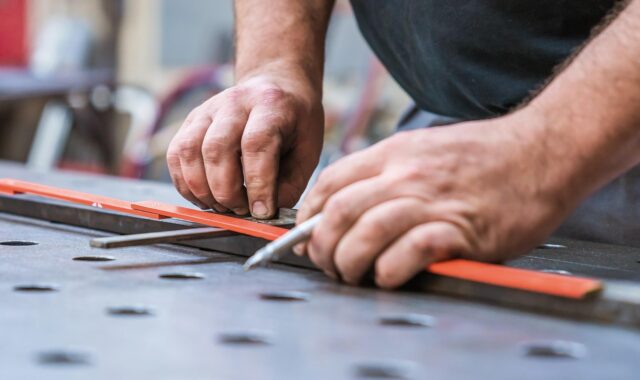
Precision engineering & manufacturing guide to tolerances, quality systems, and digital workflows
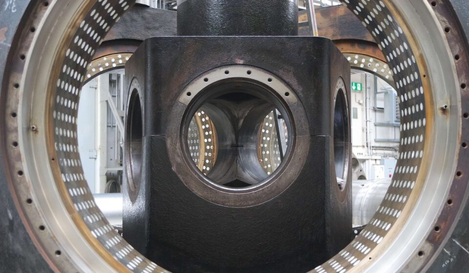
What precision engineering and manufacturing means in practice
Precision engineering & manufacturing turns functional requirements into repeatable parts, assemblies, and production processes. It connects engineering design, tolerance definition, machining or forming capability, metrology, quality management, and production data. A precise component is not automatically a good component. It has to meet the right tolerance for the application, be manufacturable at the required volume, and remain consistent across lots.
That is why modern precision work depends as much on documentation, inspection strategy, and process feedback as it does on advanced machines. For readers following industrial production trends, precision engineering is a useful lens because it shows how design choices become measurable manufacturing outcomes. The practical question is not simply “How tight can we make it?” It is “Which dimensions, surfaces, materials, and process controls matter to performance, cost, and reliability?”
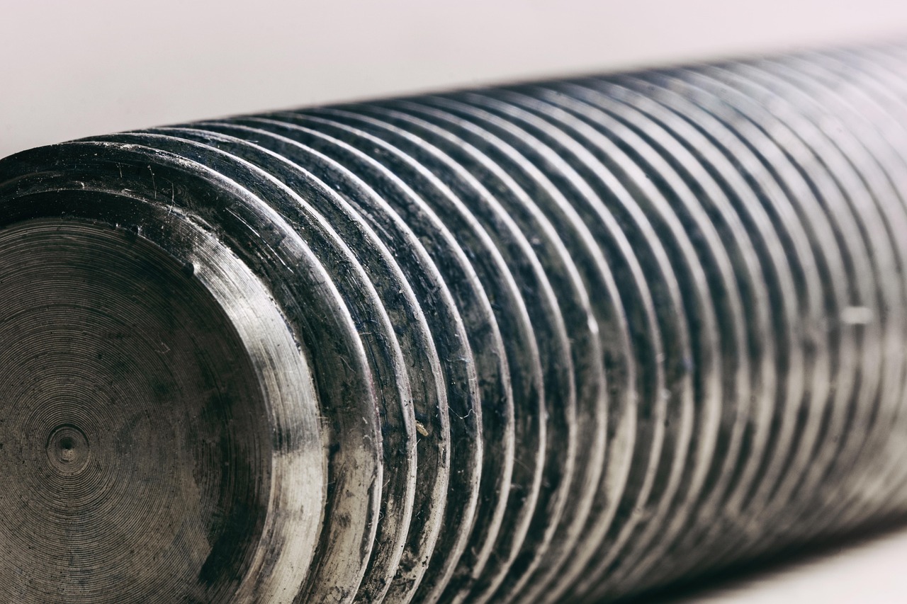
Why tighter tolerances are not always better
A common mistake in precision manufacturing is assuming that every dimension should be controlled as tightly as possible. In production, unnecessary tight tolerances can increase setup time, inspection burden, scrap risk, tool wear, and supplier cost. They can also create confusion when drawings do not clearly separate critical-to-function features from noncritical geometry.
Good precision engineering starts with what the part must do. A bearing seat, sealing face, optical mount, turbine component, medical device feature, or robotics transmission element may need tight control because small variation affects assembly, performance, wear, or safety. A clearance surface, cosmetic edge, or nonfunctional pocket may not need the same control. The value is in applying tolerance where it protects function, not in making every number smaller.
This is where tolerance stack-up analysis becomes important. Individual parts may meet their own drawings, yet the final assembly can still fail if the combined variation across parts exceeds the design allowance. In high-value manufacturing, engineers often review the full chain of dimensions, datums, fits, and assembly sequence before releasing drawings to production.
- Functional tolerance protects how a part performs in an assembly.
- Manufacturing tolerance reflects what a process can repeatedly achieve.
- Inspection tolerance accounts for measurement uncertainty and verification method.
- Commercial tolerance balances performance, production cost, and supplier capability.
The standards and documentation layer
Precision work depends on a shared technical language. Standards do not replace engineering judgment, but they reduce ambiguity between designers, machinists, inspectors, suppliers, and customers. Public materials from ISO describe ISO 9001 as a quality management system standard used across sectors, including manufacturing. ASME Y14.5 and related Y14 standards are widely used references for dimensioning and tolerancing practices, especially where geometric dimensioning and tolerancing is specified. ISO 286-1 establishes an ISO code system for tolerances on linear sizes for features such as cylinders and two parallel opposite surfaces.
For manufacturers, the key point is practical: drawings, model-based definitions, purchase orders, and inspection plans should identify the applicable standard and edition. If a contract requires one interpretation and a supplier assumes another, the disagreement may not appear until first-article inspection, production approval, or field failure analysis. Clear documentation reduces that risk.
GD&T as a manufacturing communication system
Geometric dimensioning and tolerancing is often treated as a drawing technique, but its real purpose is communication. A well-applied datum structure tells production and inspection teams how a part is functionally located. Position, flatness, perpendicularity, profile, runout, and other controls describe allowable variation in ways that simple plus-minus dimensions may not capture.
GD&T improves precision only when it is applied consistently. Overuse can make drawings harder to interpret, while underuse can leave critical relationships undefined. A sound approach is to apply geometric controls to features that affect assembly, motion, sealing, alignment, interchangeability, or measurement repeatability.
Quality systems make precision repeatable
A quality system is not the same as an inspection department. It defines how requirements are reviewed, how processes are controlled, how nonconforming output is handled, and how improvement actions are documented. ISO 9001-type quality management thinking is useful because it emphasizes consistent processes, customer requirements, documented responsibilities, and continual improvement. In precision manufacturing, those ideas translate into controlled work instructions, calibrated equipment, inspection records, traceability, corrective action, and change management.
From design intent to process capability
A precision drawing is useful only if a process can produce it repeatedly. Process capability links design intent to shop-floor reality. CNC milling, turning, grinding, EDM, laser processing, additive manufacturing, lapping, honing, and micro-machining all have different strengths. Material behavior, thermal expansion, fixturing, tool deflection, machine condition, coolant strategy, and operator setup can all affect final geometry.
Precision engineering teams therefore need to evaluate both nominal accuracy and variation. A machine may hold a tight dimension in a short trial, but production capability depends on stability over time. Temperature changes, tool wear, batch-to-batch material differences, and measurement method can shift results after the first acceptable part.
| Engineering decision | Manufacturing impact | Verification question |
|---|---|---|
| Datum scheme | Defines fixturing and inspection reference points | Can production and metrology use the same functional references? |
| Surface finish requirement | May require grinding, polishing, lapping, or controlled cutting parameters | Does the specified finish relate to sealing, wear, fatigue, or appearance? |
| Material selection | Affects machinability, stability, heat treatment, distortion, and tool life | Will the material remain stable after machining and finishing? |
| Tolerance range | Influences cycle time, scrap rate, inspection load, and supplier cost | Is the tolerance necessary for function or inherited from a legacy drawing? |
| Inspection method | Determines speed, uncertainty, and data usefulness | Can measurement variation be separated from process variation? |
The best time to resolve these questions is before production release. Design for manufacturability reviews, supplier feedback, and early metrology planning often prevent expensive changes later. Precision engineering is therefore front-loaded: decisions made in the CAD model and drawing can determine whether production becomes stable or difficult.
Metrology is part of the manufacturing system
Inspection is sometimes treated as a final gate. In precision manufacturing, it should be part of the control loop. Coordinate measuring machines, optical measurement systems, surface roughness instruments, laser scanners, air gauges, roundness testers, and in-process probing each have roles depending on geometry, tolerance, material, and production volume.
The key limitation is measurement uncertainty. If the measurement method is not accurate enough relative to the tolerance, pass-fail decisions become unreliable. A part close to the tolerance limit may be accepted by one setup and rejected by another. That is why gauge repeatability and reproducibility studies, calibration programs, environmental control, and inspection planning matter.
First-article inspection and production feedback
First-article inspection verifies that initial production output matches documented requirements. It is especially important when a new supplier, new toolpath, new fixture, revised drawing, or changed material route is introduced. Still, first-article approval does not guarantee long-term stability. Production feedback should track trends such as tool wear, dimensional drift, surface finish variation, nonconformance patterns, and rework frequency.
When measurement data flows back to engineering and process planning, manufacturers can adjust offsets, revise fixtures, improve tool strategies, or clarify drawings. When inspection data is isolated, the same defects are more likely to repeat. See also: cnc and robotics.
Digital workflows and model-based manufacturing
Digital manufacturing is changing how precision information moves through organizations. Instead of relying only on 2D drawings, many manufacturers are using 3D models, product manufacturing information, digital inspection plans, and machine-readable data to connect design, production, and quality. NIST materials on smart manufacturing and model-based enterprise emphasize interoperability, trusted data, standards, and the ability to connect product needs with process capabilities.
The value of digital workflows is not automation for its own sake. The value is reducing translation errors. If tolerances, datums, material notes, inspection requirements, and revision status can move from engineering to CAM, CMM programming, enterprise systems, and supplier portals with fewer manual reentries, the risk of mismatch decreases.
Where digital precision can still fail
Digital systems can make weak practices faster. If the original model has unclear design intent, if tolerances are copied without review, or if revision control is poor, a connected workflow can spread errors more efficiently. Precision manufacturers still need disciplined release processes, standard naming conventions, access control, training, and human review of critical requirements.
Supplier readiness is another limitation. Some suppliers can work directly from model-based definition, while others still require fully detailed 2D drawings. A practical transition strategy may include both, with a clear statement of which document controls in case of conflict.
Materials, thermal effects, and surface integrity
Precision is not only dimensional. Material behavior can determine whether a part stays within specification after machining, heat treatment, coating, assembly, or service. Aluminum, stainless steel, titanium, hardened steels, engineering plastics, ceramics, and composites respond differently to cutting forces, temperature, stress relief, and finishing operations.
Thermal effects are especially important. A part measured warm from machining may not have the same dimensions after it returns to a controlled inspection environment. Large parts, thin walls, tight bores, precision ground surfaces, and assemblies with mixed materials can be sensitive to temperature gradients. Process planning should account for stabilization time, coolant control, clamping distortion, and inspection environment.
Surface integrity also matters. A dimension may be correct while the surface has burrs, microcracks, recast layers, residual stress, or roughness that affects fatigue, sealing, friction, or cleanliness. In aerospace, medical, semiconductor, optics, and high-performance motion systems, the surface condition can be as important as the measured size.
How to evaluate a precision manufacturing plan
A strong precision manufacturing plan connects requirements to evidence. It identifies which features are critical, how they will be made, how they will be measured, and how the process will remain stable. For engineers, buyers, and production teams, the following checklist helps separate a robust plan from a vague claim of capability.
- Requirement clarity: The drawing or model identifies the controlling standard, revision, datums, material, finish, and inspection requirements.
- Manufacturing route: The process sequence accounts for roughing, finishing, stress relief, heat treatment, coating, cleaning, and final inspection.
- Capability evidence: The supplier or internal team can show relevant historical capability, trial data, or a realistic validation plan.
- Metrology alignment: Inspection methods match tolerance difficulty, part geometry, and production volume.
- Change control: Revisions, substitutions, tooling changes, and nonconformance decisions are documented.
- Feedback loop: Measurement data is reviewed to detect drift and improve the process, not only to sort good parts from bad parts.
The conclusion is straightforward: precision engineering and manufacturing works best as a system. Machines matter, but they are only one element. The strongest results come when design intent, standards, process capability, metrology, material behavior, and digital information are aligned before production problems appear.
Frequently asked questions
Is precision engineering the same as CNC machining?
No. CNC machining is one possible production method within precision manufacturing. Precision engineering also includes design intent, tolerance strategy, material behavior, metrology, quality systems, documentation, and process control.
Does a tighter tolerance always mean a better part?
No. A tighter tolerance is valuable only when it protects function, assembly, reliability, or safety. Unnecessary tight tolerances can increase cost, lead time, scrap, and inspection complexity without improving performance.
Why is GD&T important in precision manufacturing?
GD&T helps define allowable variation in form, orientation, location, and profile relative to functional datums. When applied correctly, it reduces ambiguity between design, production, inspection, and suppliers.
What role does metrology play beyond final inspection?
Metrology provides feedback for process control. It helps identify drift, tool wear, fixture issues, material distortion, and unclear requirements before problems spread through production.
How do digital workflows improve precision manufacturing?
Digital workflows can reduce manual reentry and interpretation errors by carrying model, tolerance, revision, and inspection information through design, CAM, quality, and supplier systems. Their value depends on strong data governance and clear engineering intent.