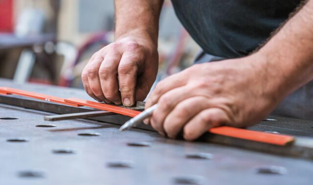
Precision engineering technologies that are changing mechanical manufacturing
Why precision engineering technologies matter now
Precision engineering technologies are no longer confined to specialist laboratories or the final inspection room. In mechanical manufacturing, they now influence how parts are designed, machined, measured, corrected and documented, from the first CAD model to the final quality record. The practical change is integration. CNC machining, advanced metrology, additive manufacturing, sensors, model-based definition and digital manufacturing systems are becoming parts of one verification-driven workflow.
For manufacturers, the goal is not simply to hold tighter tolerances. It is to make precision repeatable, traceable and economically justified across prototypes, low-volume production and complex assemblies. Many modern components run into problems not because a machine cannot cut accurately, but because design intent, process capability and inspection evidence are not aligned. A useful precision engineering strategy starts with function, converts it into measurable specifications, controls variation during production and closes the loop with verified data.
The core technology stack behind modern precision engineering
Precision manufacturing depends on a stack of technologies, not a single machine or software platform. Each layer reduces a different source of uncertainty: geometry, temperature, tool wear, fixture error, material behavior, human interpretation or data loss. The following map shows how key technologies contribute and where their limits commonly appear.
| Technology area | Primary role in precision engineering | Common limitation |
|---|---|---|
| High-accuracy CNC machining | Produces controlled geometry through stable motion, tooling and process planning | Accuracy can drift with heat, vibration, tool wear and fixturing error |
| In-process measurement | Detects variation before the part leaves the machine or cell | Requires calibration, environmental control and good measurement strategy |
| Coordinate and surface metrology | Verifies form, position, size and surface condition against specifications | Inspection plans can be slow or incomplete if not tied to functional requirements |
| Additive and hybrid manufacturing | Creates complex geometry and can reduce assemblies or enable repair | Material properties, surface finish and repeatability often need post-processing and validation |
| Model-based definition and digital thread | Connects design authority, tolerances, process data and inspection records | Value depends on disciplined data structure and supplier adoption |
| Closed-loop process control | Uses measurement and sensor feedback to adjust machining or production parameters | Poor sensor placement or weak process models can create false confidence |
High-accuracy CNC machining and hybrid platforms
Advanced CNC machining remains the foundation for many precision components. Modern machine tools combine rigid structures, thermal compensation, high-resolution feedback, multi-axis control and software-assisted toolpaths. Five-axis machining helps reduce setups, which can reduce errors introduced by repeated fixturing. Mill-turn and hybrid platforms can also combine operations that previously required several machines.
Machine accuracy, however, is only one part of part accuracy. A nominally precise machine can still produce inconsistent results if the workholding is unstable, the cutter deflects, the shop environment changes or the inspection method does not measure the functional feature. Mature shops increasingly treat machining parameters, fixtures, tools, measurement routines and environmental controls as one system.
In-process measurement and closed-loop control
In-process measurement moves verification closer to production. Probes, laser systems, displacement sensors, acoustic monitoring, power monitoring and vision systems can identify tool wear, feature drift or abnormal cutting behavior earlier than final inspection. This is especially valuable when the cost of scrapping a finished part is high, or when a feature becomes inaccessible after later operations.
Closed-loop control goes further by using measurement data to compensate the process. Typical actions include updating tool offsets, adapting feed rates, checking fixture location or stopping a cycle when sensor signals move outside the accepted window. Public research programs such as NIST smart manufacturing have emphasized measurement science, in-process sensing, monitoring and model-based control as building blocks for more reliable production systems. The manufacturing lesson is straightforward: feedback is useful only when the measurement is traceable and the correction logic is understood.
Additive manufacturing and post-processing
Additive manufacturing has become an important precision engineering technology when geometry, weight reduction, internal channels or part consolidation matter. Metal powder bed fusion, directed energy deposition and related processes can create forms that are difficult or impossible to machine from solid stock. Additive manufacturing does not remove the need for precision engineering; it usually changes where the precision problem appears.
Printed parts often need stress relief, machining, surface finishing, heat treatment and dimensional verification. Research activity around additive manufacturing metrology, including NIST work on additive manufacturing monitoring and testbeds, reflects a key industrial challenge: build data, process signatures, material condition and final geometry must be connected before additive parts can be qualified with confidence. For many manufacturers, the most realistic near-term model is hybrid production: additive for geometry or repair, machining for critical interfaces and metrology for qualification.
Digital thread and model-based definition
A digital thread links product definition, manufacturing planning, machine data, inspection results and revision history. Model-based definition, often called MBD, can reduce ambiguity by placing tolerances, surface requirements and manufacturing notes directly into the 3D product definition instead of relying only on separate 2D drawings. This becomes especially important when suppliers, quality teams and production cells must interpret complex geometry in the same way.
Digital continuity does not automatically create precision. Data must be structured, version-controlled and readable by downstream systems. If a tolerance is modeled but not understood by inspection software, or if a supplier works from an outdated file, the digital thread becomes a digital risk. Strong implementations combine model authority with disciplined change control, validated translators and inspection plans that reflect the same design intent.
Standards and verification make precision repeatable
Precision engineering depends on a shared language for defining and verifying geometry. In North American practice, ASME Y14.5-2018 is widely used for geometric dimensioning and tolerancing. It provides rules and symbols for communicating allowable variation in features such as form, orientation, location and profile. In international workflows, the ISO GPS framework serves a similar purpose by connecting specifications and verification for product geometry. ISO 14978:2018, for example, addresses general concepts and requirements for GPS measuring equipment.
These standards matter because precision cannot be managed if people disagree about what must be measured. A drawing that calls for a tight size tolerance but leaves datum structure unclear may still produce parts that do not assemble consistently. A model that contains detailed surfaces but lacks functional tolerance logic may encourage over-machining in some areas and under-control in others.
A strong verification plan usually answers four questions before production begins:
- Which features control fit, motion, sealing, stiffness, heat transfer or alignment?
- Which tolerances are truly functional, and which are inherited from past designs?
- Which measurement method is capable of detecting the relevant variation?
- How will inspection data be fed back into process improvement?
This is where precision engineering technologies have their greatest combined effect. A CNC machine can hold a process window, a CMM or optical system can quantify deviation, standards can define the acceptance rule and digital records can show whether capability is stable over time.
Where these technologies create the most value
Not every part needs advanced precision engineering. The best return appears where geometric variation has a direct effect on performance, safety, assembly time or downstream cost. In aerospace and turbomachinery, small changes in profile, surface finish and alignment can affect airflow, vibration or fatigue life. In medical devices and surgical instruments, repeatable dimensions and surfaces support fit, handling and sterilization requirements. In semiconductor equipment, motion systems, vacuum interfaces and thermal structures often require precise geometry and material stability. See also: cnc and robotics.
Precision engineering also supports electrification and advanced mobility. Electric motors, battery manufacturing equipment, power electronics cooling plates and lightweight structures can all require tight control of flatness, concentricity, sealing surfaces or thermal interfaces. In tooling and mold making, accurate surfaces and predictable shrinkage compensation influence the quality of many downstream parts, not just the tool itself.
The common thread is risk. When variation creates expensive rework, field failure, assembly bottlenecks or qualification delays, precision technologies become more than capital equipment; they become a risk-reduction system. Applying the highest possible precision everywhere is rarely efficient. Over-specification can increase cost without improving function, especially when tolerances are copied from legacy drawings rather than justified by analysis or measurement evidence.
A practical framework for selecting precision engineering technologies
Manufacturers evaluating new technology should avoid starting with the machine catalog. A more reliable approach starts with the performance requirement and works backward to the process.
- Define the functional requirement. Identify the feature or relationship that affects fit, motion, leakage, wear, stiffness, heat flow or appearance.
- Translate function into specifications. Use appropriate GD&T, surface texture requirements and material specifications instead of relying on general tight tolerances.
- Measure current capability. Compare actual production data with the required tolerance, including setup variation, environmental effects and measurement uncertainty.
- Locate the dominant source of variation. Determine whether the issue comes from machine motion, tooling, fixturing, thermal growth, material distortion, programming, inspection or human interpretation.
- Select the enabling technology. Choose CNC upgrades, better fixturing, probing, surface metrology, additive preforms, software integration or closed-loop control only after the constraint is known.
- Validate with production-like conditions. Prove the method across real materials, operators, shifts, lot sizes and inspection routines.
- Maintain traceability. Keep records that connect design revisions, process settings, measurement results and nonconformance decisions.
This framework helps prevent a common mistake: buying accuracy without improving capability. A more precise machine may not solve a thermal problem. A better scanner may not fix an unclear datum scheme. A digital platform may not improve yield if inspection results are not linked to process adjustments. Precision engineering is most effective when technology choices are tied to a verified source of variation.
Limits, risks and implementation challenges
The main limitation of precision engineering technologies is not their technical potential but their dependence on disciplined implementation. Sensors can produce large volumes of data without meaningful insight. Additive manufacturing can produce complex geometry that is difficult to inspect. Automated inspection can accelerate decisions while also spreading a flawed measurement plan more quickly. Model-based workflows can reduce drawing ambiguity, but only if the entire supply chain can read and apply the product definition correctly.
Measurement uncertainty is another critical issue. When tolerances become very small, the measurement system must be capable enough to distinguish real part variation from measurement noise. Temperature, cleanliness, fixturing force, probe strategy, surface reflectivity and operator procedure can all influence results. For high-value parts, environmental control and calibration discipline may be as important as the production equipment itself.
There is also an organizational challenge. Precision engineering connects design, manufacturing, quality and purchasing. If design teams specify features without understanding process capability, production may overwork the part. If quality teams inspect without understanding function, they may collect data that does not prevent failures. If purchasing evaluates suppliers only on unit price, the cost of variation may appear later as rework, delays or warranty risk.
Frequently asked questions
What are precision engineering technologies?
They are the combined tools, methods and standards used to design, manufacture, measure and control parts with predictable accuracy. In mechanical manufacturing, this can include high-accuracy CNC machining, precision metrology, GD&T, surface measurement, sensors, additive manufacturing, model-based definition and closed-loop process control.
Is precision engineering the same as high-tolerance machining?
No. High-tolerance machining is one part of precision engineering, but precision engineering is broader. It includes deciding which tolerances are necessary, selecting suitable processes, controlling variation, verifying results and maintaining traceable data. A part can be tightly machined and still fail if the wrong feature was controlled.
How does metrology support precision engineering?
Metrology provides the evidence that a part or process meets the required specification. Coordinate measurement, optical inspection, surface texture analysis and in-process probing help manufacturers understand variation. The value of metrology increases when the inspection plan is tied to functional features and when results are used to improve the process.
When should manufacturers consider additive manufacturing for precision parts?
Additive manufacturing is worth considering when part complexity, internal features, lightweighting, consolidation or repair value outweigh the added challenges of material qualification, finishing and inspection. For many precision applications, additive works best as part of a hybrid route that includes machining and rigorous verification.
What is the biggest mistake in adopting precision engineering technologies?
The biggest mistake is treating precision as an equipment purchase instead of a system problem. Better machines, sensors or software help only when specifications are clear, measurement is reliable, variation sources are understood and production data is used to improve decisions.