Factory layout drawing guide for manufacturing material flow and safety
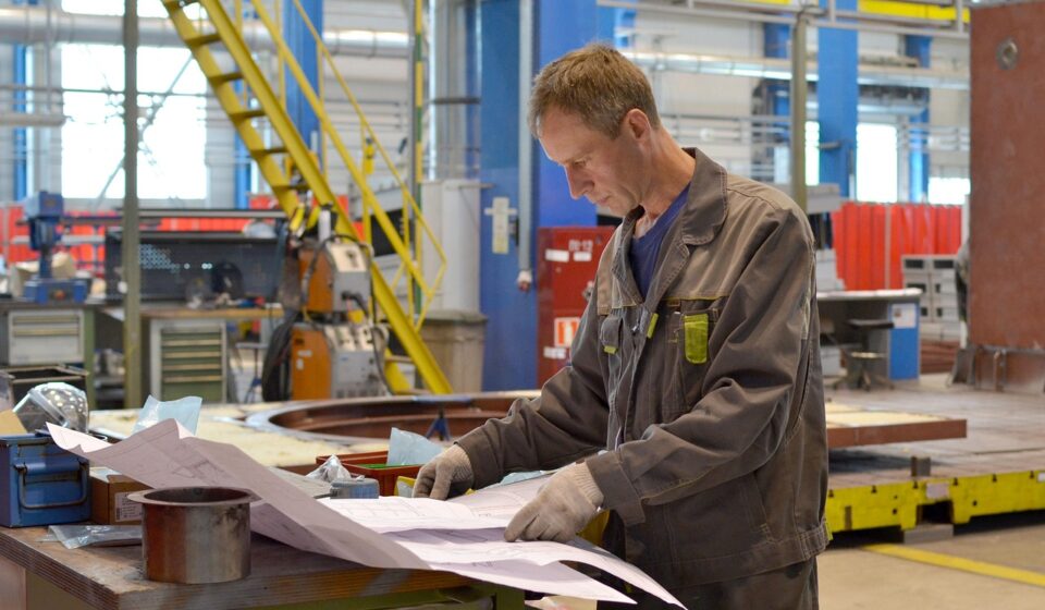
What a factory layout drawing should decide
A factory layout drawing is a scaled working plan that shows how equipment, people, materials, storage, utilities, and safety routes fit together inside a production space. For manufacturers, its value is not a neat arrangement of machines. It should help the team decide where work starts, how material moves, where work-in-process waits, how operators reach the job, how maintenance will be performed, and where traffic risks may appear before anything is bolted to the floor.
In mechanical manufacturing, the most useful drawing is usually a layered decision document: one layer for the building shell, one for process flow, one for equipment envelopes, one for forklifts or carts, one for utilities, and one for safety. This article explains how to prepare and review a practical factory layout drawing without turning it into a decorative CAD file that fails on the shop floor.

Why the drawing matters before equipment is moved
Moving a CNC machine, press, assembly bench, washer, robot cell, or inspection station is expensive because the move rarely involves only that machine. It may also affect foundations, compressed air, electrical drops, extraction, coolant lines, chip handling, access doors, operators, forklifts, and emergency routes. A layout error found during installation can quickly become a schedule problem. A layout error found after production starts can become a daily source of waste.
Public manufacturing guidance from organizations such as NIST describes factory design as a process that links equipment selection, flow planning, and facility layout. Lean guidance from NIST MEP and the Lean Enterprise Institute also treats value stream mapping as a way to visualize both material flow and information flow. In practical terms, the factory layout drawing should not start with the question, “Where can this machine fit?” It should start with, “What flow are we trying to create, and what constraints must the layout respect?”
For a machining or fabrication site, the drawing can directly influence travel distance, queue size, part damage, crane congestion, floor visibility, and quality response time. A short route on paper is not enough. The route must match load size, container type, turning space, lifting method, inspection points, and move frequency.
Inputs to collect before drawing the future layout
A useful drawing starts with verified inputs. If the team draws from assumptions, the CAD model may look precise but still be wrong. The following inputs should be checked before layout alternatives are compared.
- Building constraints: column grid, wall locations, dock doors, ramps, pits, drains, floor flatness issues, slab capacity, ceiling height, mezzanines, fire doors, and fixed offices.
- Process route: the normal path for each product family, including receiving, cutting, machining, heat treatment, cleaning, inspection, assembly, packing, and shipping where relevant.
- Equipment data: footprint, operating envelope, door swing, guarding, loading side, service side, maintenance pull-out space, weight, vibration sensitivity, and utility requirements.
- Material data: raw material length, pallet size, bin type, lifting points, finished goods packaging, scrap flow, returnable containers, and special handling risks.
- People and traffic: operator work zones, pedestrian paths, forklift routes, tugger routes, crane coverage, visitor routes, and supervision sight lines.
- Safety and compliance needs: emergency access, marked passageways, guarding, lockout access, eyewash or emergency equipment locations, and separation between pedestrians and powered vehicles.
OSHA general industry requirements emphasize clean, orderly walking-working surfaces and the correction of hazardous conditions before employees use those surfaces. OSHA material handling and powered industrial truck requirements also affect how aisles, storage, and vehicle movement are controlled. Exact requirements depend on the operation, jurisdiction, equipment type, and local code review, so the drawing should be reviewed by qualified safety and facilities personnel rather than treated as an engineering guess.
Choose the layout logic before choosing the final shape
A factory layout drawing should express how the plant is intended to operate. Different manufacturing environments need different layout types. A job shop handling low-volume, high-variety work should not be forced into the same drawing logic as a dedicated assembly line. Likewise, a cell layout may support flow for a product family, but it can create problems if material supply, inspection, or shared equipment is ignored.
| Layout approach | Where it fits | What the drawing must show clearly |
|---|---|---|
| Product or line layout | High-volume, repeatable routing with stable demand | Sequence, pitch spacing, line-side material, rework loops, and bottleneck protection |
| Process or functional layout | Job shops, repair work, or varied routing by machine type | Shared equipment access, queue locations, travel distance, and dispatching visibility |
| Cellular layout | Product families with similar routing and moderate variation | Operator movement, one-piece or small-batch flow, material presentation, and cross-training zones |
| Fixed-position layout | Large products such as heavy assemblies, tooling, or structures | Crane reach, kit staging, mobile equipment access, and safe work envelopes around the product |
| Hybrid layout | Plants combining machining, fabrication, assembly, inspection, and shared support areas | Interfaces between departments, supermarkets, transport loops, and rules for shared resources |
The drawing does not need to make one layout type look perfect. It needs to make trade-offs visible. For example, grouping all machining centers may simplify maintenance and tooling support, while placing selected machines in a product cell may reduce transport and waiting. The better choice depends on actual routing, demand stability, staffing model, and the cost of shared resources.
A practical workflow for creating the drawing
Start with the current state
Before creating the future plan, document the current state. A simple current-state layout, route map, or spaghetti diagram can reveal travel paths that the team has stopped noticing. Walk the floor, measure real distances, record common waiting points, and note where operators leave the workstation to fetch tools, gauges, drawings, fixtures, or packaging.
For existing factories, this step is especially important because the official drawing may not match the floor. Machines may have been moved, temporary storage may have become permanent, and utilities may have been modified without updating the master layout. The current-state drawing should be verified physically, not only inherited from an old file.
Block the flow before detailing the machines
In the early stage, use blocks instead of detailed equipment symbols. Blocks make it easier to compare receiving, storage, production, inspection, packing, and shipping relationships without getting distracted by exact machine geometry. This is where from-to charts, route frequency, product families, and value stream maps are useful.
The goal is to reduce unnecessary movement without creating unsafe congestion. A straight line is not always best if it creates crossings between forklifts and pedestrians, forces heavy loads through narrow areas, or leaves no room for WIP control. At this stage, compare at least two or three realistic alternatives rather than polishing the first idea.
Convert the preferred option into a scaled layout
Once the flow logic is selected, convert it into a scaled factory layout drawing. Use real machine dimensions and include maintenance envelopes, operator zones, access panels, guarding, loading areas, and doors. Show fixed objects such as columns, pits, electrical rooms, fire equipment, restrooms, offices, and docks. If a machine requires a foundation, isolation pad, crane service, or special ventilation, mark that requirement early.
A good drawing separates permanent features from flexible features. Heavy equipment, pits, cranes, and main utility runs are difficult to change. Benches, carts, point-of-use racks, visual boards, and small supermarkets may be easier to adjust after launch. The drawing should protect flexibility where future product mix or volume is uncertain.
Review with operations, safety, maintenance, and quality
The layout should be reviewed by the people who will live with it. Operators can identify awkward reaches and missing point-of-use items. Maintenance can spot blocked panels, poor access for service carts, or crane limitations. Quality can identify where inspection, containment, calibration, and nonconforming material need space. Safety can review walking-working surfaces, vehicle separation, guarding access, emergency routes, and housekeeping risks.
NIOSH and OSHA ergonomics materials both recognize that workstation layout, reaches, posture, tools, and material handling can contribute to strain. That means an equipment layout is not complete if it ignores the human task. A workstation that looks compact may still be poor if operators twist, reach, lift, or walk excessively during every cycle. See also: cnc and robotics.
Validate before installation
Validation can be as simple as a taped floor mock-up or as advanced as a digital model. For complex lines, simulation or digital twin methods can help test capacity, congestion, equipment interaction, and reconfiguration scenarios before physical installation. NIST has described digital twins in manufacturing as a way to represent complex systems using sensors, modeling, simulation, and industrial data. Smaller factories may not need a full digital twin, but they can still validate the layout with scaled templates, cardboard mock-ups, pilot cells, and operator walkthroughs.
Details that are easy to miss in a factory layout drawing
Many layout problems come from small omissions rather than a completely wrong concept. When reviewing the drawing, check the following details carefully.
- Maintenance access: show space for opening panels, replacing motors, pulling filters, removing chip conveyors, and bringing in service equipment.
- Material staging: mark where raw material, kits, empty containers, finished goods, scrap, rework, and quarantined product will actually sit.
- Traffic crossings: identify where pedestrians, forklifts, tuggers, carts, and cranes interact. Crossings are not automatically unacceptable, but they require controls.
- Utilities: include compressed air, power, data, water, gas, ventilation, dust extraction, coolant, drainage, and lighting where they affect placement.
- Quality control points: leave space for gauges, inspection tables, calibration storage, sample retention, and nonconforming material control.
- Line-side presentation: show how parts arrive at the operator, not only where the machine sits. Racks, carts, bins, and label orientation matter.
- Future expansion: reserve realistic space for added machines, automation, inspection equipment, or higher-volume material handling.
Vertical space is another detail that is often missed. A plan view may show floor area, but cranes, robot envelopes, overhead doors, ducting, cable trays, mezzanines, lighting, and sprinkler clearance can determine whether the layout is buildable. If vertical conflicts are likely, the drawing set should include elevation views or a 3D model.
Common mistakes to avoid
The first mistake is drawing machines before drawing flow. This often produces a tidy arrangement that increases transport, hides bottlenecks, or creates too many handoffs. The second mistake is using average demand only. Layouts designed only around averages may fail during peak mix, rush orders, changeovers, or shared-equipment conflicts.
The third mistake is ignoring temporary states. Installation, ramp-up, maintenance shutdowns, engineering trials, and abnormal quality holds all require space. If the normal layout uses every square meter, any disruption will spill into aisles and work zones. The fourth mistake is treating the drawing as finished after installation. A factory layout drawing should be controlled like an operating document, with revision dates, owners, and a process for updating it when equipment or routes change.
Finally, avoid copying a layout from another plant without checking constraints. A layout that works in one facility may depend on a different product mix, building shape, labor model, material handling system, or utility infrastructure. Benchmarking is useful, but the final drawing must be based on the actual operation.
What a complete drawing package should include
For a small improvement project, one well-annotated layout may be enough. For a plant move, new line, or major re-layout, the drawing package should be more complete. A practical package often includes:
- a current-state layout showing the existing arrangement and main problems;
- a future-state block layout showing the intended flow logic;
- a scaled equipment layout with machine envelopes and access zones;
- a material flow or traffic plan showing routes, staging, and crossings;
- a utility plan identifying major service requirements and constraints;
- a safety review layer showing exits, emergency access, guarding, and marked passageways;
- an equipment schedule listing asset names, dimensions, weights, utility needs, and move status;
- a phased installation plan showing what can move first and what must remain operational.
This package turns the drawing into a communication tool. Operations can see how production will run, facilities can estimate installation work, safety can review hazards, finance can understand scope, and management can compare options before committing capital.
Frequently asked questions
What is the difference between a factory layout drawing and a normal floor plan?
A normal floor plan mainly shows the physical space. A factory layout drawing shows how manufacturing work will operate inside that space, including machines, material movement, workstations, storage, utilities, access, and safety routes.
Which software should be used for a factory layout drawing?
The right tool depends on project complexity. Simple improvement projects can start with scaled 2D drawings, while major relocations or automated lines may benefit from CAD, BIM, simulation, or 3D modeling. The tool matters less than accurate data, disciplined layers, and review by the right stakeholders.
Who should approve the layout before installation?
Approval should involve operations, engineering, maintenance, safety, quality, facilities, and any team responsible for utilities or material handling. For regulated processes or building changes, code, environmental, fire protection, or external engineering review may also be required.
Does every factory layout need simulation?
No. Simulation is valuable when capacity, congestion, automation, routing variation, or investment risk is high. For smaller layouts, a measured drawing, route analysis, mock-up, and shop-floor review may provide enough confidence.
How often should the drawing be updated?
The drawing should be updated whenever equipment, routes, storage areas, aisles, utilities, or safety controls change. Many factories also benefit from a scheduled layout audit so that the official drawing does not drift away from the real floor.