Factory plant layout planning for safer flow and flexible production
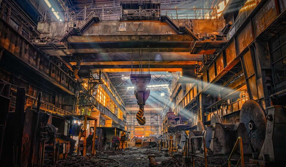
What a factory plant layout must achieve
A factory plant layout is more than a machine arrangement on a floor plan. In mechanical manufacturing, it is a working system that connects product routing, material movement, labor, inspection, storage, utilities, maintenance access and safe emergency movement. A good layout reduces unnecessary travel, makes bottlenecks easier to see, lowers avoidable handling risks and leaves room for future product or volume changes. OSHA’s general industry material-handling rule requires sufficient safe clearance where mechanical handling equipment is used, and its emergency exit guidance requires exit routes to remain unobstructed. Those requirements make safety clearances and flow paths basic layout inputs, not details to add after the equipment is placed. (osha.gov)
The practical starting point is straightforward: plan around how value moves through the plant, then check whether people, equipment, forklifts, cranes, utilities and emergency access can support that movement without creating conflicts.
Start with routing and product families before moving equipment
Many layout projects begin too late, with a narrow question such as “Where should this new machining center fit?” A better first question is “Which products, parts or assemblies should flow together?” Mechanical factories often have mixed routings. Sawing, turning, milling, heat treatment, grinding, washing, inspection, assembly and packing may not occur in the same sequence for every part. If the layout only reflects departmental ownership, the result can be long transport loops, hidden work in process and repeated staging.
Before drawing a new arrangement, collect a small but reliable data set: product families, annual or monthly demand, routing steps, lot sizes, changeover frequency, material dimensions, handling method, queue points and quality checkpoints. A simple from-to chart or spaghetti diagram can show whether high-volume or high-frequency flows are crossing the building unnecessarily. The goal at this stage is not a perfect mathematical model. It is to separate the few flows that dominate daily movement from the many flows that occur only occasionally.
Product-family logic is especially useful in mechanical manufacturing because different parts may use similar machines but require different handling rules. A compact precision component may move by cart or tote, while a welded frame may need crane coverage and larger turning radii. Treating both as one generic material flow can produce a layout that looks efficient on paper but fails during actual handling.
Choose a layout type that matches production behavior
Factory plant layout decisions usually combine several layout types. The right choice depends on variety, volume, routing stability, equipment cost, handling difficulty and the need for flexibility. The table below summarizes common options for mechanical manufacturing.
| Layout type | Typical fit | Main advantage | Main risk |
|---|---|---|---|
| Process or functional layout | High-mix machining, job shops, shared specialist equipment | Flexible use of expensive machines and skilled labor | Long travel, complex scheduling and more work in process |
| Product or line layout | Stable sequence, higher volume, repeatable assembly or finishing | Clear flow, easier pacing and lower handling effort | Less flexible when product mix or routing changes |
| Cellular layout | Part families with similar routings and repeatable demand patterns | Shorter travel and stronger ownership of flow | Can duplicate equipment or underuse capacity if families are poorly defined |
| Fixed-position layout | Large equipment, heavy fabrications, large molds or projects that cannot move easily | Reduces movement of the main product | Requires careful planning of tools, workers, cranes and temporary storage |
| Hybrid layout | Most real factories with mixed products and shared constraints | Balances flow, flexibility and equipment utilization | Needs clear rules for shared resources and internal logistics |
Cellular manufacturing is often discussed in lean production because it groups machines, people and tools around a product family instead of a traditional department. The U.S. Environmental Protection Agency’s lean manufacturing guidance describes cellular manufacturing as a shift away from batch-and-queue production toward product-aligned flow and pull production. This does not mean every factory should become fully cellular. It means cells are worth testing when a stable family of parts repeatedly travels between the same processes. (epa.gov)
A layout can also be partly cellular and partly functional. For example, a factory may keep large heat-treatment, coating or coordinate measuring equipment as shared resources while creating cells for repeat machining and assembly families. This hybrid approach is often more realistic than forcing every process into one format.
Build safety and ergonomics into the first layout draft
Safety is easier to design into a layout than to retrofit after installation. A mechanical factory has many potential conflict points: forklift traffic near pedestrians, crane movement over staging zones, sharp material edges, hot work, compressed air lines, chip handling, coolant spills, welding fumes, noise and maintenance access around guarded machinery. OSHA’s material-handling rule specifically addresses safe clearances for aisles, loading docks, doorways and turns where mechanical handling equipment is used, and it states that stored material must not create a hazard. (osha.gov)
Emergency movement also belongs in early layout planning. OSHA’s emergency exit route guidance states that exit routes must be unobstructed by materials, equipment, locked doors or dead-end corridors. In layout terms, temporary staging, packing, maintenance carts and overflow inventory cannot be allowed to consume the paths that people need during abnormal events. (osha.gov)
Ergonomics should be treated as a layout issue, not only as a workstation issue. CDC/NIOSH explains that ergonomic intervention requires understanding work processes, job tasks, equipment and workplace layouts, and it recommends ergonomics programs as a supplement to occupational health and safety management systems. For a factory layout, this leads to practical checks: minimize repeated manual carrying, reduce twisting between operations, keep frequently used tools within easy reach, use height-appropriate benches and place heavy or awkward items where mechanical assistance is available. (cdc.gov)
Design material handling as a system, not a side activity
Material handling often takes more space than early layout drawings show. A machine footprint may be fixed, but the working footprint includes loading space, operator space, in-process stock, chip bins, pallets, carts, inspection stands, tool cabinets, maintenance access and safe travel paths. If these areas are not shown in the first draft, they usually appear later as aisle congestion and informal storage.
A stronger approach is to define the handling system together with the equipment layout. Decide which flows need forklifts, pallet jacks, carts, conveyors, cranes, automated guided vehicles or manual totes. Then test the layout against actual turning needs, pickup points and delivery frequency. Where forklifts and pedestrians must share a zone, the plan should consider marked walkways, visibility at corners, speed controls, mirrors, barriers and separated crossings where feasible.
Internal logistics should also cover empty containers, returnable packaging, scrap, rework, tools and quality holds. These reverse and side flows are easy to overlook, but they can disrupt the main production route if they do not have assigned space. A compact production cell with no place for rejects or tool changes will quickly become cluttered, even if the process sequence is correct.
Plan utilities, maintenance and quality checkpoints early
Plant layout quality is often decided by constraints that are not visible in a simple machine map. Mechanical manufacturing equipment may need foundations, compressed air, extraction, coolant supply, electrical drops, network connections, temperature control, metrology stability, crane access, chip removal and preventive maintenance clearance. Moving a machine into a good flow position is not useful if the location cannot support safe maintenance or stable process conditions.
Quality control also needs a defined place in the layout. In some plants, inspection belongs near the process to support fast feedback. In others, precision measurement may require a controlled environment away from vibration, dust or temperature swings. The layout should distinguish between quick in-process checks, final inspection, quarantine, calibration storage and customer documentation areas.
Digital readiness is another practical consideration. Even a traditional machining plant may use barcode scans, tool management systems, machine monitoring, digital work instructions or production dashboards. The layout should allow operators to capture data at the point where the information is created, rather than at a distant terminal after the fact. This is a planning principle, not a universal rule: the right level of digital integration depends on the plant’s size, product risk and management system.
Validate the layout before committing capital
A factory plant layout should be tested before machines are moved, utilities are rerouted or concrete is cut. Start with a current-state map, then build two or three layout alternatives. For each option, compare travel distance, number of handling touches, forklift crossings, WIP locations, operator walking, maintenance access, emergency routes, installation cost and disruption during changeover.
Useful validation methods include scaled floor plans, CAD blocks, cardboard mockups, operator walkthroughs, forklift path checks, crane coverage reviews and time studies for high-frequency routes. For high-investment projects, discrete-event simulation may help test queue behavior and capacity assumptions. However, simulation should not replace direct observation. If the input data are weak, a sophisticated model can still produce a misleading answer.
The most valuable layout review usually includes production, maintenance, quality, safety, logistics and operators. Each group sees different failure modes. Maintenance may notice a blocked service panel. Quality may see that inspection feedback will arrive too late. Operators may recognize that a cart route crosses a chip bin or that a tool cabinet is on the wrong side of the machine. These comments are not minor preferences; they are early warnings about daily execution.
A practical checklist for factory plant layout review
- Define product families and dominant routings before placing equipment.
- Separate high-frequency flow from occasional or exceptional flow.
- Show the full working footprint, not only the machine footprint.
- Mark aisles, pedestrian routes, forklift paths, loading areas and emergency exits.
- Assign space for WIP, tools, scrap, rejects, empty containers and maintenance carts.
- Check crane reach, turning radius, door clearance and dock movement where relevant.
- Confirm utilities, foundations, ventilation, chip handling and environmental needs.
- Locate inspection points where they support fast feedback and product protection.
- Review the plan with operators, maintenance, quality, logistics and safety staff.
- Compare alternatives using measurable criteria rather than preference alone.
For more manufacturing layout and factory operations topics, visit PODUAI.
Frequently asked questions
What is the difference between factory layout and plant layout?
In everyday manufacturing use, the terms often overlap. “Factory layout” usually emphasizes the arrangement of production areas, machines, people and material flow inside the factory. “Plant layout” can be broader, including buildings, utilities, docks, warehouses, service areas and sometimes the relationship between multiple production zones on one site.
Which factory plant layout is most suitable for mechanical manufacturing?
There is no single layout type that fits all mechanical factories. A high-mix machine shop may need a functional layout with strong dispatching and material control. A repeat assembly area may benefit from a line layout. A family of parts with similar routing may justify a cellular layout. Many factories use a hybrid layout because shared equipment, heavy handling and varied demand make one pure model unrealistic.
How often should a factory layout be reviewed?
A layout should be reviewed when product mix changes, new equipment is added, volume shifts, safety incidents suggest flow conflicts, material handling becomes congested or quality feedback is delayed. A formal annual review can be useful, but event-based review is more important than following a fixed calendar.
What is the most common layout mistake?
A common mistake is optimizing machine placement while ignoring the space around the machine. Operators, tools, pallets, chips, fixtures, inspection gauges, maintenance access and safe travel paths all require space. If these needs are not shown in the plan, the factory may gain a tidy drawing but lose daily operating efficiency.
Can a small factory improve layout without a major relocation?
Yes. Many improvements come from clearer staging rules, better point-of-use storage, reduced walking, marked aisles, relocated tools, smaller batch movement and improved separation between people and vehicles. Small changes should still be checked against safety, utility and maintenance requirements before implementation.