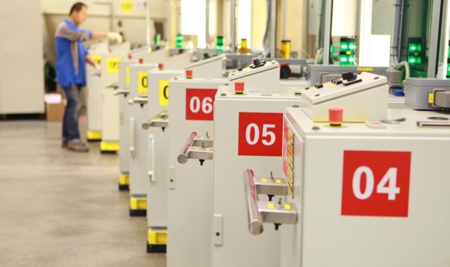
How to plan a factory layout around factory machinery

Factory machinery should come before the floor plan
Factory machinery is not simply equipment placed inside a finished building. It determines how materials enter and leave each process, where operators stand, how utilities are routed, how maintenance teams reach service points, and where safety controls must be installed. A practical factory layout starts with each machine’s process role, footprint, service clearance, guarding needs, energy sources, loading method, and connection to upstream and downstream operations.
Only after those details are clear should teams finalize aisle widths, storage points, workstations, inspection areas, and expansion zones. Planning in this order reduces avoidable rearrangement, supports safer work, and makes the layout easier to adjust when production volume, product mix, or automation levels change.
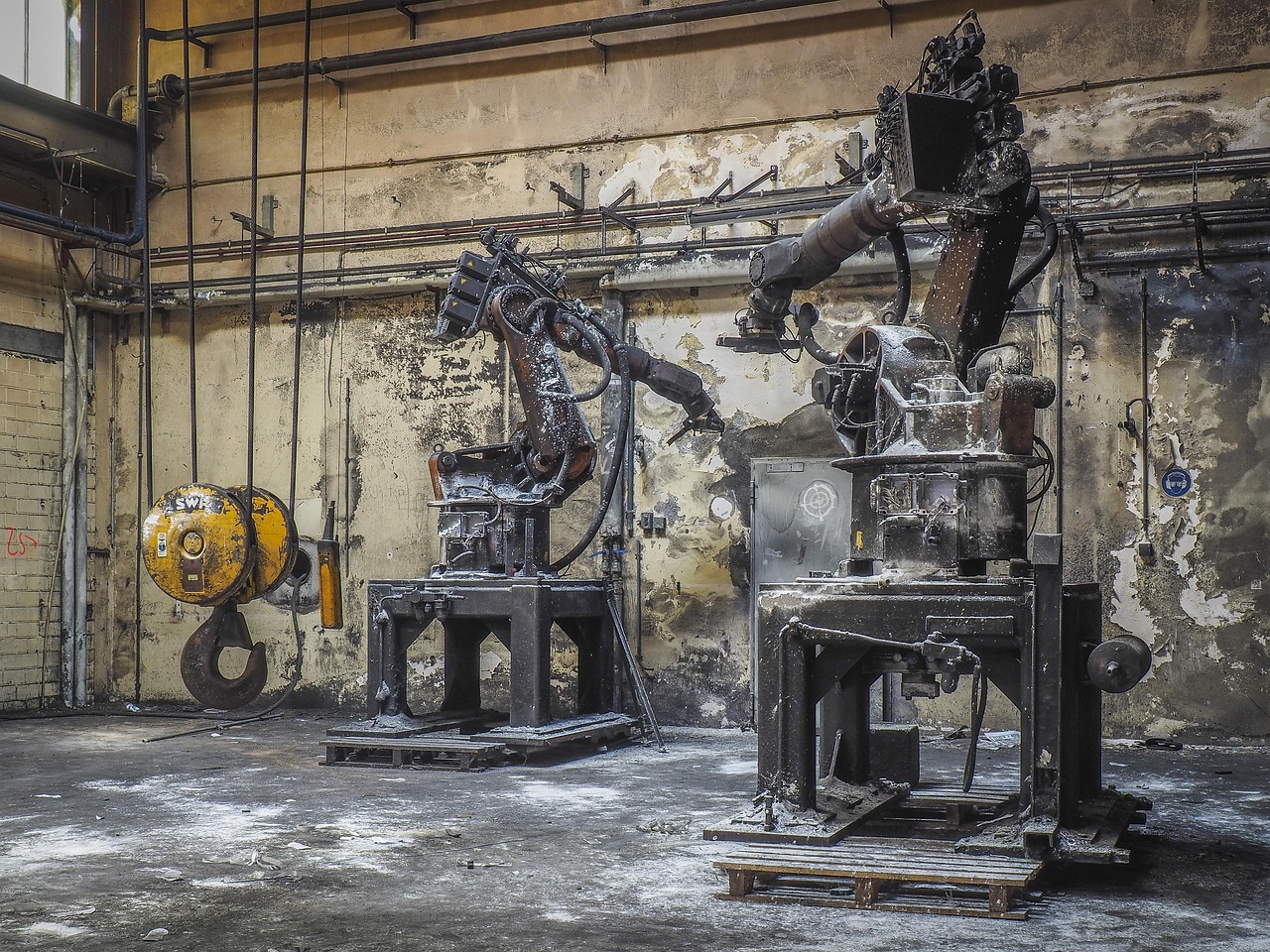
For more layout-focused manufacturing guidance, see the factory layout section.
Start with process flow, not machine size alone
A common mistake in machinery layout planning is treating the largest machines as isolated blocks on a drawing. Size matters, but process sequence usually matters more. A heavy press, CNC machining center, assembly cell, welding station, packaging line, or inspection machine may appear to fit in the available space while still causing delays because the material path is indirect or the support work is too far away.
A useful first step is to list each machine in the order in which a product or component actually touches it. For each step, note whether material arrives by forklift, pallet jack, conveyor, crane, robot, cart, automated guided vehicle, or manual handling. Then identify the output form: loose parts, palletized work, totes, finished assemblies, scrap, rework, or inspected goods. This simple map helps show whether the layout should be linear, U-shaped, cellular, functional, or a hybrid.
For high-volume and stable processes, a more linear arrangement can reduce handling and make visual control easier. For high-mix production, functional departments or flexible cells may be more practical because machines must serve different product families. The better layout is not always the one with the shortest theoretical travel distance. It is the one that supports real scheduling, operator movement, quality checks, and material replenishment with the least avoidable friction.
Build a machinery data table before drawing the layout
A machinery data table turns layout planning from guesswork into a controlled decision. It should include more than machine length and width. Doors, panels, coolant tanks, chip conveyors, feeder bowls, robot reach envelopes, guarding, electrical cabinets, exhaust points, compressed air, lubrication access, tool change areas, and maintenance removal paths can all affect placement. These details often determine whether a machine that appears to fit will actually work in daily operation.
| Data point | Why it matters for layout |
|---|---|
| Machine footprint | Defines the base occupied area, including fixed frames and support equipment. |
| Operating clearance | Allows operators to load, unload, adjust, inspect, and respond to faults. |
| Maintenance clearance | Prevents service work from blocking main aisles or requiring machine relocation. |
| Utility needs | Guides routing for power, compressed air, water, gas, ventilation, drainage, and data. |
| Material input and output direction | Determines whether the machine aligns with the process flow or creates backtracking. |
| Safety and guarding zones | Protects workers from moving parts, flying chips, stored energy, and robot motion. |
| Noise, heat, dust, fumes, or vibration | Helps separate incompatible processes and plan extraction, isolation, or foundations. |
| Future change potential | Identifies machines likely to need added feeders, automation, inspection, or buffers. |
This table is also useful when comparing new and existing equipment. Older machinery may lack the compact utilities, integrated guarding, or data interfaces of newer equipment. Newer automation, however, may require more perimeter space, fencing, sensors, and safe access routes than expected. A data table makes these trade-offs visible before installation.
Plan safety access as part of the layout, not after installation
Machine safety should not be treated as a late-stage checklist. In the United States, OSHA’s machinery and machine guarding requirements address hazards such as points of operation, rotating parts, ingoing nip points, flying chips, and sparks. OSHA’s lockout/tagout framework also addresses hazardous energy during servicing and maintenance. These requirements affect layout because workers must be able to operate, isolate, inspect, and maintain equipment without entering unnecessary danger zones.
A layout should reserve space for guards, interlocked gates, light curtains, emergency stops, lockout points, electrical disconnects, maintenance platforms, and safe fault recovery. If a machine is placed too close to a wall, column, rack, or aisle, a maintenance task may force workers into awkward positions or expose them to nearby traffic. If an electrical cabinet opens into a busy forklift route, a service activity can become a traffic hazard.
Safety planning should also separate normal production access from maintenance access. Operators usually need quick, repeated access for loading, unloading, inspection, and adjustment. Maintenance technicians may need deeper access to drives, motors, hydraulic units, pneumatic components, sensors, filters, tool magazines, or robot controllers. A layout that supports both groups reduces informal workarounds, which are often a sign that the floor plan does not match the work being done.
Match machinery layout with material handling and storage
Factory machinery rarely works alone. Every machine needs a material handling method, a place for incoming work, a place for outgoing work, and a way to remove scrap, chips, packaging, or rejected parts. When these support zones are missing, aisles become temporary storage, operators walk farther, and supervisors lose visibility of work in progress.
The right buffer size depends on production rhythm. A continuous line may need small, controlled buffers to protect flow without hiding problems. A job shop may need more staging space because order sequence changes throughout the day. A fabrication area may need separate zones for raw plate, cut blanks, fixtures, consumables, and finished weldments. A machining area may need tool carts, coolant support, chip handling, inspection benches, and quarantine space for nonconforming parts.
Material handling equipment should be planned with the same care as production machinery. Forklifts need turning space and clear sightlines. Overhead cranes need hook coverage, lift height, and load path planning. Conveyors need access for cleaning and jam recovery. Mobile robots and automated guided vehicles need stable routes, charging areas, sensor visibility, and rules for interaction with pedestrians. If handling equipment is added after the layout is fixed, it often competes with operators for the same space.
Utilities, foundations, and environment can decide where machines belong
A machine that fits the floor area may still be in the wrong location if utilities, foundations, or environmental conditions are ignored. Heavy machinery may require floor loading review, vibration isolation, anchor points, pits, or crane access. Precision inspection equipment may need separation from vibration, heat, dust, or direct airflow. Welding, cutting, painting, grinding, and chemical processes may need ventilation, extraction, fire protection, drainage, or controlled separation from other operations.
Utility routing also affects long-term flexibility. Overhead drops can make reconfiguration easier in some facilities, while trenching or fixed piping may make future changes more expensive. Electrical panels, compressed air headers, data networks, coolant systems, dust collectors, and exhaust ducts should be located so that maintenance remains accessible. A low-cost installation path that blocks service access can become expensive over the life of the equipment. See also: cnc and robotics.
Environmental effects should be mapped as zones. Heat-generating machines can affect nearby operators or measurement processes. Noisy equipment can influence communication and hearing protection needs. Dust and mist can affect sensors, controls, finished surfaces, and worker exposure. Machines with vibration can disturb precision machining, inspection, or assembly. A layout that recognizes these interactions is more reliable than one that simply fills open space.
Design for digital readiness and future changes
Modern factory machinery is increasingly connected to production planning, quality systems, maintenance systems, and data collection platforms. NIST smart manufacturing work has emphasized the relationship between physical plant layout and information-system layout, especially when equipment, software, inspection, and production control must exchange data. In practical terms, the floor plan should support not only where machines sit, but also how information moves to and from them.
Digital readiness does not require every facility to install advanced automation immediately. It means reserving practical pathways for data cables, wireless coverage, sensor mounting, control cabinets, operator terminals, barcode or RFID points, and inspection feedback loops. It also means avoiding layouts that make future automation physically difficult. For example, a machine cell that may later add a robot should leave space for guarding, part presentation, end-of-arm tooling storage, controller access, and safe entry points.
Future change is especially important for manufacturers facing shorter product life cycles or wider product variety. Instead of designing only for today’s equipment list, layout planners should identify which machines are stable anchors and which areas should remain flexible. Heavy machines with expensive foundations may be difficult to move, while light assembly benches, inspection stations, racks, and carts can be designed as modular elements. Separating fixed infrastructure from flexible work areas helps the factory evolve without a full redesign.
A practical checklist for placing factory machinery
The following checklist can help teams review a machinery layout before installation, relocation, or expansion:
- Confirm the process sequence and product families before placing major equipment.
- Record the full machine envelope, including doors, panels, feeders, conveyors, guards, cabinets, and service zones.
- Check operator access for normal loading, unloading, adjustment, inspection, and cleaning.
- Check maintenance access for lockout points, panels, motors, fluids, sensors, tooling, and replacement parts.
- Separate pedestrian movement from forklift, crane, cart, or mobile robot routes wherever practical.
- Reserve controlled space for incoming material, outgoing work, scrap, rework, inspection, and quarantine.
- Review utility routing for power, compressed air, water, gas, drainage, ventilation, dust collection, and data.
- Map hazards such as moving parts, stored energy, noise, heat, fumes, chips, sparks, dust, vibration, and blind corners.
- Validate floor loading, anchoring, vibration, lift access, and installation paths before equipment arrives.
- Leave realistic room for future tooling, automation, inspection, software integration, or product changes.
This checklist should be used with input from production, maintenance, safety, quality, engineering, logistics, and operators. Each group sees different failure points. Operators may know where loading becomes awkward. Maintenance may know which panels are opened most often. Quality may know where inspection must happen before defects travel downstream. Logistics may know whether a buffer location will block replenishment. A layout becomes stronger when these viewpoints are reconciled early.
Frequently asked questions
What is the first step in laying out factory machinery?
The first step is to map the production process and material flow before placing individual machines. This shows which equipment must be close together, where buffers are needed, and which machines may create safety, utility, or handling constraints.
How much clearance should be left around machinery?
There is no single clearance that fits every machine. The required space depends on the machine envelope, guarding, operator tasks, maintenance access, utility connections, material handling method, and applicable safety requirements. Manufacturer manuals, risk assessments, and local regulations should be reviewed before final placement.
Should machinery be arranged by process or by product flow?
It depends on production type. Product-flow layouts often suit high-volume, repeatable work. Process-based layouts may suit high-mix, low-volume operations where the same machinery serves many product routes. Many factories use hybrid layouts, combining cells, shared departments, and dedicated lines.
Why does maintenance access matter in factory layout?
Maintenance access affects downtime, safety, and repair cost. If technicians cannot reach panels, motors, filters, drives, tooling, or lockout points safely, routine work takes longer and may disrupt nearby production. Service space should be planned before machines are installed.
How can a factory layout prepare for automation later?
Factories can prepare by leaving space for robots, conveyors, sensors, guarding, control cabinets, part presentation, data networks, and safe access gates. Even if automation is not installed immediately, reserving these options can reduce disruption when equipment is upgraded.
Conclusion
Effective factory layout starts with understanding the machines in detail. Footprint is only the beginning. A strong plan connects factory machinery with process flow, safety access, material handling, utilities, environmental conditions, maintenance work, and future digital integration. The result is not simply a cleaner drawing. It is a factory that is easier to operate, safer to maintain, and better prepared to adapt as production requirements change.